

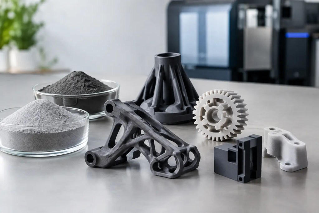
A material decision made at the quoting stage can determine whether a part survives a functional test, cleans effectively after use, or performs reliably through a production run. This guide to HP MJF materials is intended for engineers selecting polymers for functional prototypes, manufacturing aids, and end-use components. The right choice is not simply the strongest material available. It depends on loading, flexibility, chemical exposure, environmental conditions, required finish, and the production process that follows.
HP Multi Jet Fusion produces polymer parts by applying fusing and detailing agents across a powder bed, then using thermal energy to fuse each layer. The process supports complex geometries without dedicated tooling and produces parts with a dense, industrial-grade structure. However, material behavior still varies meaningfully between nylon, elastomeric, and polypropylene-based options. Selecting for the actual operating condition is the most reliable way to avoid unnecessary redesigns.
What HP MJF Material Selection Controls
Material selection affects more than a data-sheet value. It influences wall thickness decisions, snap-fit geometry, surface appearance, tolerance strategy, finishing options, and the consistency of a short-run build. A rigid housing, for example, may prioritize stiffness and dimensional stability. A wearable enclosure may need toughness and a less brittle response under impact. A fluid-handling component may place chemical resistance above cosmetic appearance.
MJF is especially effective when teams need repeatable polymer parts without the lead time and upfront commitment of injection molding. It is well suited to low-volume production, but it should not be treated as a direct substitute for every molded resin. Molded material grades, fiber reinforcement, color systems, and highly specialized additives may not have an equivalent MJF option. Where the requirement is specific, validate the printed material against the assembly and its use environment rather than assuming a familiar polymer name will deliver identical results.
Guide to HP MJF Materials: Core Options
PA12: the balanced engineering nylon
PA12 is often the default MJF material for good reason. It combines strength, toughness, dimensional stability, and fine feature capability in a balanced engineering polymer. It is a practical choice for functional prototypes, enclosures, brackets, clips, jigs, fixtures, and complex assemblies where a rigid part must tolerate routine handling.
PA12 generally offers lower moisture uptake than PA11, helping it maintain predictable properties in many typical applications. It also supports a broad range of post-processing routes, including bead blasting, dyeing, painting, vapor smoothing where applicable, and coating. That flexibility is useful when the same part must progress from an engineering prototype to a customer-facing, short-run product.
The trade-off is that PA12 is not the best option for every impact-critical or highly flexible design. Thin, repeatedly flexed sections may fatigue over time, especially if geometry concentrates stress. For living hinges, soft-touch interfaces, or parts that must flex substantially in service, consider TPU or PA11 instead.
PA11: toughness and ductility for demanding use
PA11 is a nylon selected when ductility, impact performance, and resistance to repeated deformation take priority. Compared with PA12, it typically provides a more flexible response before failure. This makes it suitable for clips, snap features, protective components, prosthetic and orthotic applications, and geometries exposed to shock or repeated loading.
For a part with integral snaps, PA11 can provide more design margin than a stiffer nylon. That does not eliminate the need for good snap-fit design. Root radii, deflection limits, engagement geometry, and print orientation still affect performance. But PA11 is often the better starting point when the feature must flex repeatedly rather than simply hold a static load.
PA11 can be a strong choice for end-use components, but moisture conditioning and the service environment should be considered during validation. Nylon properties can shift with absorbed moisture. If a tight functional specification depends on stiffness or fit, test parts after conditioning them in conditions representative of actual use.
TPU: flexible parts with elastic recovery
TPU is the MJF option for elastomeric behavior. It is appropriate for flexible ducts, vibration isolators, gaskets, protective covers, grips, seals, and compliant mechanisms. Its ability to deform and recover makes it fundamentally different from PA12 or PA11, so it should be designed as an elastomer from the outset rather than used as a flexible substitute for a rigid plastic part.
The key engineering question is not whether TPU is flexible, but how much flexibility the application needs. A part that must seal against a mating surface, absorb impact, or bend through repeated cycles benefits from a compliant material. Conversely, a part that needs precise positional control, threaded connections, or rigid datum surfaces may require a nylon design with a separate elastomeric component.
TPU can require different dimensional allowances and finishing expectations than nylon. Flexible walls may distort under measurement or assembly load, and soft surfaces can show handling marks more readily. Provide the intended hardness range, compression requirement, and mating conditions during review so the material and design can be evaluated together.
Polypropylene: chemical resistance and lightweight flexibility
Polypropylene is valuable where low density, chemical resistance, and fatigue performance are central to the requirement. It is particularly relevant to fluid-contact components, laboratory accessories, containers, ducting, and parts that encounter cleaning agents or industrial chemicals. Its resistance profile can make it a better candidate than nylon for selected chemical environments.
Like conventional polypropylene, MJF polypropylene has a relatively low modulus compared with engineering nylons. It is therefore less suitable where high stiffness, tight structural support, or threaded load capacity is required. Its dimensional behavior and surface characteristics also call for application-specific review. For fluid-related parts, printed polymer should never be assumed to be fully leak-tight without testing. Geometry, wall thickness, finishing, and pressure all influence the outcome.
Filled nylon grades: stiffness where it matters
Some MJF workflows support glass bead-filled PA12 or similar filled nylon options. These materials increase stiffness and can improve dimensional stability, making them useful for housings, fixtures, brackets, and components that must resist deflection. They are often selected when a standard nylon part is structurally sound but feels too compliant under load.
The trade-off is reduced ductility. Filled materials are generally less appropriate for snap fits, impact-prone edges, and parts requiring repeated flexing. They may also have a different surface appearance and machining response. Use them to control deflection, not as a universal upgrade over standard PA12.
Select Material From the Failure Mode Backward
The most efficient selection process starts by defining how the part could fail. If it might crack after an impact, compare PA11 and PA12. If it bends repeatedly, assess TPU or PA11. If it sees solvents, detergents, or process fluids, evaluate polypropylene and confirm compatibility with the specific chemical, concentration, temperature, and exposure duration. If it must hold alignment under load, PA12 or a filled nylon may be more appropriate.
Temperature deserves the same level of attention. A part that performs on a desk may soften, creep, or lose stiffness in an enclosed machine, vehicle cabin, or heated production area. Consider the continuous service temperature, peak exposure, load during heat exposure, and cooling cycles. Heat resistance is not one number in practice. A lightly loaded cover and a stressed mounting bracket can behave very differently at the same temperature.
For assemblies, identify which interfaces carry risk: screw bosses, snap fits, bearing surfaces, sealing faces, or thin cantilevers. These local features often determine success more than the bulk material property. A material recommendation is strongest when it is tied to these interfaces and the real load case.
Design and Finish Are Part of the Material Decision
MJF parts emerge from the powder bed with a matte surface and a fine granular texture. This is acceptable for many functional applications, but post-processing may be needed for appearance, cleanability, friction control, or assembly fit. Bead blasting removes residual powder. Dyeing and painting can improve appearance. Smoothing or coatings may be considered where a more refined surface or reduced porosity is needed.
Finishing changes dimensions and surface behavior, particularly on small holes, thin gaps, threads, and sealing surfaces. Specify critical dimensions, cosmetic faces, and post-processing requirements before production. A tolerance that is achievable in the raw state may need a different allowance after coating, smoothing, or machining.
Design orientation also matters. MJF generally offers more balanced mechanical behavior than many extrusion-based processes, but orientation, thermal history, geometry, and nesting can still influence results. Critical components should be built to a defined production approach, inspected against agreed requirements, and validated in their intended orientation.
Qualify Parts Before Committing to Production
For a first functional build, use representative geometry rather than a simple coupon alone. Include the snap, boss, seal, hinge, thin wall, or mating feature that drives the application. Test the part after the planned post-processing route, because raw and finished surfaces can behave differently in fit, friction, and appearance.
A controlled path from prototype to repeat production reduces procurement risk. At Additive3D Asia, ISO 9001:2015 quality processes and material-specific manufacturing workflows support traceable decisions from CAD review through final delivery. For production-facing programs, document the selected material, finish, inspection criteria, revision level, and any agreed process constraints so that subsequent orders are built to the same intent.
Choose the material that addresses the component’s most credible failure mode, then prove it in the assembly. That approach produces more dependable parts than selecting on tensile strength alone.