
A prototype that passes a bench test but cannot be manufactured consistently is not a finished engineering decision. When learning how to prototype low volume parts, the objective is not simply to get a physical model quickly. It is to produce enough representative parts to validate fit, function, material behavior, assembly, and the likely production route without committing to expensive tooling too early.
For engineering teams, low-volume prototyping usually means anywhere from a few parts to several hundred. The best process depends on what the parts must prove. A cosmetic enclosure, a load-bearing bracket, a fluid-handling manifold, and an assembly fixture may all begin from the same CAD workflow, but they demand very different manufacturing methods, materials, tolerances, and inspection plans.
Start With the Decision the Parts Must Support
Before requesting a quote, define the question the prototype needs to answer. This prevents a common failure: ordering high-detail visual models when the team actually needs functional parts for thermal, mechanical, or assembly testing.
Early-stage concept models can prioritize speed and appearance. Functional prototypes should match the expected loading, temperature range, chemical exposure, and fastening method as closely as possible. Engineering validation builds may require controlled dimensions, documented inspection, and repeatability across multiple units. If the goal is a pilot run or market trial, the prototype should also test production realities such as finishing time, assembly labor, packaging, and yield.
State these requirements directly in the manufacturing brief: intended quantity, critical dimensions, expected loads, environmental conditions, surface requirements, and target delivery date. A clear brief gives an engineering team the information needed to recommend a process rather than simply manufacture the supplied geometry.
How to Prototype Low Volume Parts by Process
No single technology is optimal for every low-volume requirement. The right choice balances geometry, material performance, surface quality, dimensional control, quantity, and cost per part.
Polymer additive manufacturing for fast functional iteration
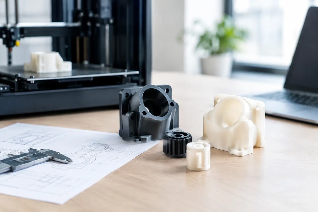
For complex polymer components, additive manufacturing often provides the fastest path from CAD to usable parts. HP Multi Jet Fusion and selective laser sintering are particularly suitable for functional enclosures, brackets, ducting, clips, jigs, and assemblies with internal channels or lattice features. PA12 is a common choice for durable parts with good general chemical resistance and stable mechanical performance. PA11 can be useful where greater ductility and impact resistance are required.
Because powder-bed processes do not require dedicated support structures in the same way as many other methods, they can produce nested assemblies and complex geometries efficiently. The trade-off is that surface texture is typically more matte and granular than a machined or molded finish. Dyeing, bead blasting, vapor smoothing, coating, or machining can improve appearance and functional surfaces where required.
SLA is better suited to high-detail visual models, smooth cosmetic surfaces, and precise small features. Material selection remains critical. A standard rigid photopolymer may look excellent but may not represent the impact resistance, long-term stability, or heat performance of the final production resin. Use it for appearance and fit validation unless the selected engineering resin has been confirmed for the intended test conditions.
FDM is often effective for large fixtures, shop-floor aids, and quick form studies. Its cost and lead time can be favorable, but anisotropic strength and visible layer lines must be considered when the part will carry load or interface with precision components.
Metal additive manufacturing for geometry-driven metal parts
Metal SLM is valuable when a part requires internal flow paths, topology optimization, weight reduction, or a geometry that would be difficult to machine from solid stock. AlSi10Mg is often selected for lightweight, complex aluminum components, while SS316L is suited to corrosion-resistant parts and industrial environments.
Metal additive manufacturing is not automatically the right answer for every metal prototype. Build orientation, support removal, heat treatment, machining allowances, and inspection requirements affect both lead time and cost. Critical bores, sealing faces, threads, and datum surfaces frequently require secondary CNC machining. Plan for these operations from the beginning rather than treating them as a late correction.
CNC machining for precision and production-representative materials
CNC machining is often the strongest choice when parts require tight tolerances, smooth surfaces, standard engineering plastics, or conventional metals. It is especially useful for precision housings, brackets, heat sinks, test fixtures, and components with critical mating features.
For low quantities, machining can be more economical than additive manufacturing when geometry is straightforward and the material must closely match a production-grade polymer or metal. It also offers a clear path to controlled tolerances on critical dimensions. The limitation is geometric access: deep internal passages, undercuts, and highly organic forms may require multiple setups, specialized tooling, or design changes.
Casting and molding for repeated parts and market testing
When a design is stable and the required quantity moves beyond a handful of units, vacuum or urethane casting can bridge the gap between additive prototypes and injection molding. It can produce multiple parts from silicone tooling with a more molded appearance and a range of polyurethane material characteristics.
For higher quantities, injection molding may be justified, particularly when production material, surface texture, and repeatability are essential. Tooling cost and lead time are the trade-offs. A low-volume program should only move to molding once the design has been sufficiently validated, because engineering changes after tool release can be expensive.
Select Materials Based on Failure Modes
Material selection should begin with how the part could fail, not with a preferred process. Identify whether the primary risk is cracking under load, creep under sustained stress, heat distortion, chemical attack, UV exposure, wear, electrical requirements, or poor cosmetic durability.
A snap-fit enclosure needs ductility and fatigue resistance around the flexible features. A fixture used near a heat source needs adequate heat deflection temperature. A threaded component may need inserts or machined threads rather than printed threads. A pressure or fluid-handling part needs attention to porosity, sealing surfaces, and post-processing.
If a final production material is not practical for the first prototype, choose a substitute that preserves the most important behavior. For example, a PA12 prototype may be appropriate for assembly and handling tests before a molded nylon design is finalized. Document the gap between prototype material and production material so test results are not interpreted beyond their limits.
Design Tolerances Into the Prototype Plan
Do not apply tight tolerances uniformly across every dimension. That increases cost without improving the function of the assembly. Instead, identify datums and critical-to-function features such as bearing seats, sealing faces, interlocking features, connector locations, and fastener patterns.
Specify general tolerances separately from critical dimensions. Ask for inspection of the features that determine whether the prototype passes or fails. For additive parts, allow for process-specific variation, orientation effects, shrinkage, and post-processing. For machined parts, consider tool access and realistic tolerance capability for the chosen material and geometry.
Design for assembly as well as individual part dimensions. A housing may measure within tolerance yet still create excessive interference when paired with a gasket, insert, mating cover, or purchased component. Where possible, test representative assemblies rather than isolated parts.
Build an Iteration Plan Before Ordering
A controlled prototype program is faster than a sequence of reactive orders. Release an initial build for major geometry and functional risks, then reserve a second build for refinements identified through testing. This approach avoids spending on cosmetic finishing or extensive inspection before core performance is verified.
Use revision control from the first order. Every CAD release should have a clear revision identifier, a documented change note, and an updated drawing when dimensions or requirements matter. Keep manufacturing feedback with the revision record, including concerns about thin walls, unsupported features, difficult tool access, distortion risk, or finishing limitations.
For parts approaching production, establish acceptance criteria before fabrication. This may include dimensional inspection points, material confirmation, finish requirements, thread verification, assembly checks, and photographs of cosmetic surfaces. ISO 9001:2015-controlled workflows are especially valuable when multiple stakeholders need traceability and repeatable results across builds.
Use One Manufacturing Partner Across the Transition
Vendor fragmentation can slow iteration. A part made by one supplier for additive prototyping, another for machining, and a third for finishing may introduce inconsistent assumptions about tolerances, materials, and acceptable appearance.
A manufacturing partner with additive and conventional capabilities can recommend when to retain the same process and when to switch. Additive3D Asia, for example, can support polymer and metal additive manufacturing alongside CNC machining, casting, sheet metal fabrication, and post-processing from the same project workflow. That breadth helps teams compare options based on part performance rather than forcing the design into a single technology.
Provide a native CAD file such as STEP when possible, along with STL files where additive manufacturing is planned. Native geometry supports more accurate manufacturability review, while clear drawings communicate critical dimensions and inspection expectations.
The strongest low-volume prototype is not necessarily the fastest or least expensive individual part. It is the one that gives your team dependable evidence for the next decision: revise the design, validate the assembly, release a pilot run, or commit to production tooling.