

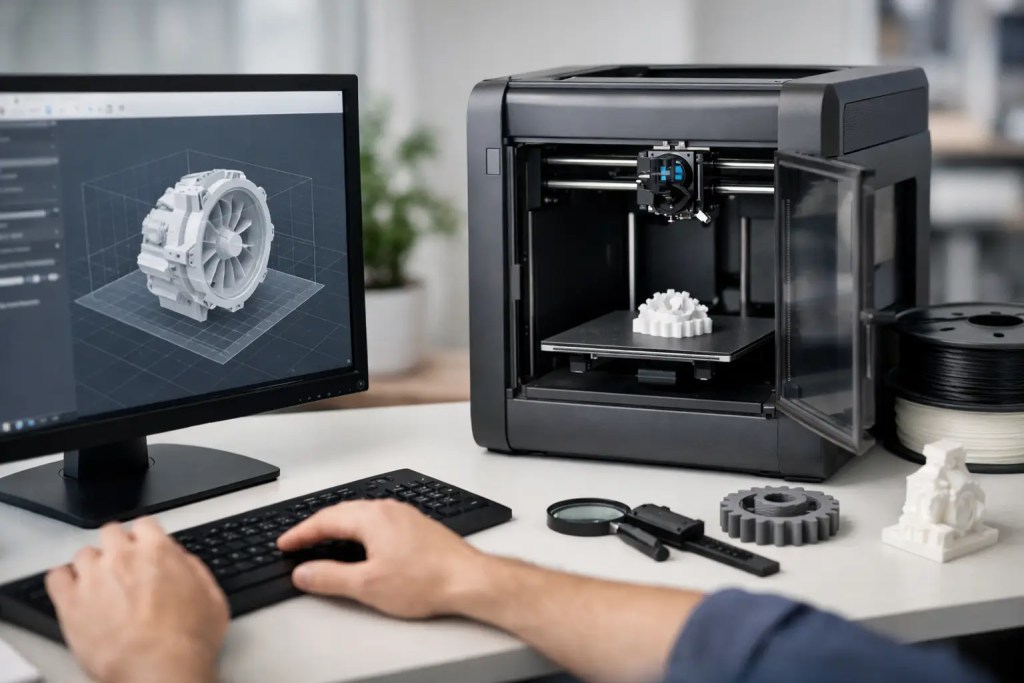
A model can look correct in CAD and still fail before production begins. When teams ask how to prepare STL for printing, the answer is not simply to export the file. The STL must accurately represent the intended geometry, suit the selected manufacturing process, and provide enough information for a supplier to produce the part repeatedly.
For prototypes, a minor file issue may only cost a day. For fixtures, short-run components, or customer-facing end-use parts, the same issue can create dimensional variation, weak features, poor surfaces, or an unnecessary redesign. A disciplined STL preparation process reduces those risks before the part reaches the build queue.
Start With the Manufacturing Requirement
Prepare the file around the part’s functional requirements, not around a default export setting. Confirm what the part needs to do: carry a load, snap onto a mating component, withstand heat, guide an assembly operation, or provide a cosmetic surface. These requirements determine the appropriate process, material, orientation, tolerances, and finishing plan.
For example, a PA12 MJF enclosure can provide strong, production-ready polymer performance with good dimensional stability. An SLA model may be a better fit where fine detail and a smooth appearance matter most. AlSi10Mg or SS316L may be appropriate for metal components requiring strength, heat resistance, or corrosion resistance. Each process imposes different limits on wall thickness, unsupported geometry, minimum feature size, and surface quality.
This decision should happen before STL export whenever possible. A file that is technically printable in one process may not be economical, durable, or accurate enough for another. If the part has critical fits, threaded interfaces, sealing surfaces, or load-bearing sections, retain the native CAD or a STEP file alongside the STL. It gives the manufacturing team a more reliable reference if geometry needs to be reviewed.
How to Prepare STL for Printing From CAD
An STL is a triangulated mesh. It approximates curved CAD surfaces with many small flat facets. The export settings control the balance between geometric accuracy and file size.
Use a fine enough chord height and angle tolerance that visible faceting does not appear on curves, holes, cylinders, or mating surfaces. At the same time, avoid exporting an unnecessarily dense mesh. Extremely high triangle counts increase upload, processing, and repair time without improving the manufactured part beyond the capability of the selected process.
The right setting depends on the part and process. A small cosmetic housing with radii and circular details needs a finer mesh than a large bracket with broad planar faces. For most engineering work, the objective is simple: the mesh should preserve the intended geometry within the practical accuracy of the printing process.
Set the export unit explicitly. Millimeters are standard for most industrial additive manufacturing workflows, but do not assume the software will transfer units correctly. A model created in inches can arrive 25.4 times too small if units are misinterpreted. Before upload, confirm the bounding dimensions against the original CAD model and the drawing.
Validate That the Mesh Is Watertight
A printable STL represents a closed volume. Every edge must connect to another edge, surface normals must point consistently outward, and the mesh must not contain self-intersections or zero-thickness regions. These are commonly described as non-manifold errors.
A slicer may attempt an automatic repair, but automatic repair is not a substitute for design review. It can close gaps, remove overlapping regions, or alter thin features in ways that change the part’s function. A repaired mesh may print successfully while no longer matching the intended design.
Check the STL for common issues before submitting it:
- Holes, open edges, or disconnected shells that prevent a closed volume
- Reversed normals that confuse inside and outside surfaces
- Intersecting bodies or duplicate internal faces
- Zero-thickness surfaces, such as a single CAD surface exported without solid volume
- Very small sliver triangles and damaged geometry around fillets or Boolean operations
Most CAD platforms and mesh inspection tools can identify these conditions. When the issue originates in the CAD feature tree, correct it in CAD and export a new STL. Editing the mesh should generally be reserved for simple repairs, scan data, or legacy geometry where the original model is unavailable.
Check Walls, Features, and Clearances
The visual appearance of a feature does not guarantee that it will survive printing and post-processing. Thin walls can warp, break during unpacking, or be removed during support removal. Small embossed text can fill in. Narrow slots may close due to process resolution, shrinkage, or finishing.
Review the part against the design guidance for the selected process and material. Unsupported walls, pins, snap features, and long slender sections deserve particular attention. A wall that performs well in MJF PA12 may require a different thickness in FDM, while an SLA feature with excellent detail may not have the impact resistance required for a functional clip.
Assemblies need a separate clearance review. Printed parts are not produced to a single exact dimension. Every process operates within a tolerance range, and orientation can affect dimensions and surface texture. Provide purposeful clearance between mating printed components. For precision fits, consider designing stock for secondary machining rather than expecting an as-printed bore or flat surface to meet a tight tolerance.
Threads are another frequent source of avoidable rework. Small threads are often better tapped after printing, while metal parts may benefit from machined threads or threaded inserts depending on load and service conditions. State the thread standard, engagement depth, and critical dimensions in the drawing or manufacturing notes.
Select an Orientation Based on Function
Build orientation affects much more than how the part fits in a machine. It influences strength direction, support requirements, surface finish, dimensional control, and cost.
For FDM, layer direction has a significant effect on tensile strength and fatigue performance. Orient load-bearing features so the primary load does not separate layers. For SLA and metal SLM, support placement can affect cosmetic surfaces and areas that require post-processing. For powder-bed polymer processes such as MJF and SLS, supports are not required, but orientation can still influence surface appearance, cooling behavior, and the accuracy of critical faces.
Identify surfaces that matter most before production: sealing faces, bearing seats, datum surfaces, visible exterior panels, and mating interfaces. Where possible, orient the design to protect those areas from supports, stair-stepping, or difficult finishing operations. There are trade-offs. The orientation that gives the best surface on one face may increase supports, lead time, or distortion elsewhere. Functional priorities should guide the decision.
Design for Post-Processing From the Start
Post-processing is part of the manufacturing route, not an afterthought. Bead blasting, dyeing, vapor smoothing, sanding, painting, machining, heat treatment, and support removal can all change surface texture, dimensions, or edge condition.
If a component needs a smooth cosmetic finish, allow sufficient material at sharp edges and avoid deeply recessed areas that are difficult to sand, coat, or clean. If it requires machining, provide accessible tool paths and identify the datums that control the final dimensions. For metal additive parts, consider where supports can be attached and removed without compromising critical geometry.
The same applies to trapped powder or resin. Hollow sections, internal channels, and enclosed cavities need properly sized escape holes where the process requires them. These openings must be positioned so material can be removed effectively, then sealed or incorporated into the final design if needed.
Include Production Information Beyond the STL
The STL communicates shape, but it does not communicate all manufacturing intent. For any part with controlled requirements, submit a drawing, STEP file, or clear production notes with the mesh. Specify critical dimensions, tolerances, material, finish, thread requirements, color, quantity, and inspection expectations.
Use general tolerances only where the part can accept them. Mark the dimensions that truly control function. Over-tolerancing every feature increases cost and may force unnecessary secondary operations. Under-specifying a critical interface leaves too much room for interpretation.
At Additive3D Asia, this information supports a faster manufacturability review across polymer and metal additive processes, as well as CNC machining and finishing where hybrid production is the better route. A clear file package lets engineering teams identify risks early rather than after the build has started.
Run a Final Preflight Before Upload
Before releasing the file, compare the STL dimensions with the CAD model, verify units, inspect the mesh, and confirm that all bodies intended for production are present. Then check that material and process selection align with the functional requirement, not simply the lowest initial price.
Name files with a controlled revision, such as PartNumber_RevB.stl, and keep the matching drawing and CAD source under the same revision. This basic discipline prevents a common production failure: printing an obsolete model after a late design change.
A well-prepared STL does not remove every engineering decision, but it gives production a stable starting point. The fastest path to dependable parts is to resolve geometry, material, orientation, and tolerance questions while they are still easy to change on screen.