
Metal printing is most valuable when a conventional process forces an engineering compromise: an assembly with too many components, an internal passage that cannot be machined, or a low-volume part whose tooling cost does not make business sense. For these applications, metal additive manufacturing can reduce part count, shorten development cycles, and produce functional components in production-grade alloys.
That does not mean it is the right answer for every metal part. Metal printing requires disciplined process selection, design-for-additive rules, post-processing, and quality control. The strongest results come from treating it as a manufacturing process with defined constraints, not as a shortcut around engineering.
What metal printing is designed to do
Industrial metal printing typically refers to laser powder bed fusion, also called selective laser melting (SLM). A recoater spreads a thin layer of metal powder across the build plate. A high-powered laser selectively melts the powder according to the digital part geometry, and the cycle repeats layer by layer until the part is complete.
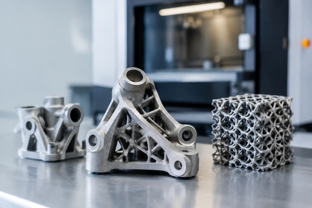
Because the part is built additively, SLM can create shapes that are impractical or impossible to manufacture by CNC machining, casting, or sheet metal fabrication alone. These include conformal cooling channels, lattice structures, enclosed flow paths, consolidated assemblies, and topology-optimized brackets.
The process is especially effective for low- to medium-volume requirements where performance, geometric freedom, or lead time carries more value than the lowest possible unit price. Aerospace hardware, medical instruments, robotics components, custom tooling, thermal management parts, jigs, fixtures, and functional prototypes are common use cases.
Material selection remains central to the decision. AlSi10Mg is often selected for lightweight parts with good thermal performance. SS316L is a practical option for corrosion resistance and durable functional components. Other alloys may be appropriate where high temperature strength, wear resistance, or specific mechanical properties are required. The material must be matched to the operating environment, loading condition, and finishing plan rather than selected on strength alone.
When metal printing is the right process
The best candidates usually have a clear technical or commercial reason to be printed. A part that combines several machined components into one can eliminate fasteners, reduce assembly labor, and remove tolerance stack-up between interfaces. A mold insert with conformal cooling can improve temperature control where straight-drilled channels cannot reach. A lightweight bracket may benefit from topology optimization if mass reduction has a measurable downstream value.
Metal printing also supports faster iteration before committing to casting or machining fixtures. Engineers can validate fit, airflow, heat transfer, or functional loads with an alloy part rather than relying only on polymer prototypes. For short-run production, the absence of dedicated tooling can make the process commercially viable even when the per-part cost is higher than high-volume manufacturing.
However, simple prismatic parts, large flat plates, and components with straightforward machined features may be better made by CNC machining. If a design needs thousands of identical parts and does not require additive-only geometry, casting, forging, or metal injection molding may offer better economics. Process selection should account for total cost, lead time, quantity, tolerances, mechanical requirements, and post-processing – not geometry alone.
Design rules that affect metal printing results
A CAD model suitable for machining is not automatically suitable for SLM. Design review before production is necessary because orientation, support strategy, wall thickness, internal channels, and powder removal all influence manufacturability.
Build orientation and support structures
Part orientation affects surface quality, build time, distortion risk, and the amount of support material required. Down-facing surfaces and shallow overhangs often need supports to anchor the part and manage heat during the build. Those supports must later be removed, which can leave witness marks and make certain surfaces less accessible.
Critical cosmetic surfaces, tight-tolerance faces, and support-sensitive geometry should be positioned with post-processing in mind. In many cases, a hybrid route is the right choice: print the near-net-shape component, then CNC machine datum surfaces, bores, threads, and sealing interfaces. This approach combines additive design freedom with the accuracy and surface finish of subtractive manufacturing.
Wall thickness, channels, and enclosed features
Thin walls can be produced, but minimum thickness depends on alloy, part size, geometry, and functional requirements. A wall that prints successfully may still be unsuitable if it deflects under load or distorts during stress relief. Engineers should design for both printability and the actual service condition.
Internal channels need sufficient diameter and a clear route for unmelted powder to escape. Blind cavities and narrow passages can trap powder, which may be unacceptable for fluid systems, moving assemblies, or regulated applications. Where internal surface finish is critical, plan for appropriate geometry, cleaning access, or alternative manufacturing methods early in the design cycle.
Tolerances and surface requirements
SLM produces near-net-shape parts, not automatically finished parts. Dimensional capability varies with feature type, orientation, geometry, and post-processing. Flatness, roundness, bore size, and thread quality should be evaluated separately from general dimensional tolerance.
Specify precision only where it matters. Applying tight tolerances across an entire drawing increases cost without necessarily improving function. Identify critical-to-function dimensions, define datums, and reserve machining allowances for surfaces that need a controlled finish. This gives the manufacturing team a practical route to verify the part against its requirements.
The post-processing plan is part of the process
A metal-printed part is not complete when it leaves the machine. After printing, parts are typically separated from the build plate, supports are removed, and the material undergoes heat treatment or stress relief as required. Surface finishing may include bead blasting, polishing, machining, coating, or other treatments based on the application.
Post-processing can determine whether a component meets its final requirements. For example, machining may be necessary for bearing seats and threaded interfaces. Bead blasting can provide a more uniform appearance, while polishing may be needed for flow-sensitive or cosmetic surfaces. Heat treatment should be selected according to the alloy and desired mechanical performance.
This is also why the lowest quoted print price is not always the lowest finished-part cost. A part with difficult-to-access supports or excessive machining requirements can lose the advantage of additive manufacturing. A manufacturability review should consider the entire production route from powder build to final inspection.
Quality control for production metal printing
For prototypes used only to assess form and fit, the inspection plan may be relatively simple. For functional or end-use components, quality expectations should be defined before production begins. Requirements can include material identification, dimensional inspection, visual inspection, surface condition, heat-treatment records, and process traceability.
A controlled quality system matters because metal additive manufacturing includes several interconnected variables: powder handling, machine parameters, build orientation, thermal treatment, support removal, and finishing. Repeatability comes from standardized workflows and documented controls, not from the machine alone.
For teams sourcing parts externally, provide the CAD model in a suitable format such as STEP or STL, along with material, quantity, drawing requirements, finishing needs, and the intended application. A clear RFQ reduces back-and-forth and gives the supplier enough context to identify risks before manufacturing starts.
At Additive3D Asia, metal SLM can be combined with CNC machining, surface post-processing, and complementary manufacturing processes under an ISO 9001:2015 quality system. That matters when a project moves from an early prototype to short-run production and needs the same manufacturing partner to manage the next process decision.
A practical decision point for engineers
Before choosing metal printing, ask a direct question: what specific constraint does additive manufacturing remove? If the answer is internal geometry, part consolidation, rapid access to an alloy prototype, lightweight performance, or tooling-free low-volume production, SLM may provide a strong return. If the answer is simply that the part is metal, another process may be more efficient.
Start with the functional requirement, then select the manufacturing route that meets it with the fewest compromises. A well-designed metal-printed part is not defined by how complex it looks. It is defined by measurable performance, a controlled production plan, and a geometry that earns the added freedom of the process.