

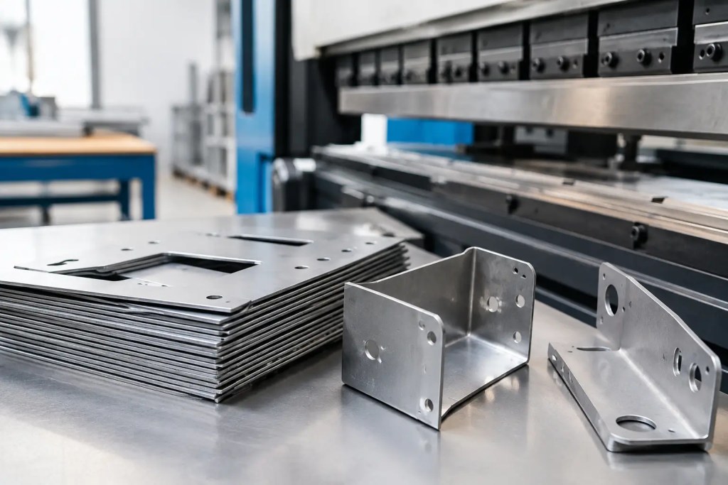
A formed enclosure that fits the first time can move a prototype into validation within days. One with an overlooked bend radius, inaccessible fastening feature, or cosmetic surface requirement can trigger a redesign and delay procurement. That is why sheet metal fabrication should be treated as an engineering decision, not simply a purchasing line item.
For brackets, panels, housings, covers, chassis, and structural assemblies, sheet metal provides an efficient route to strong, production-ready parts. The right outcome depends on matching material, forming process, tolerances, and finishing requirements to the actual function of the component.
What Sheet Metal Fabrication Includes
Sheet metal fabrication converts flat stock into finished components through a sequence of cutting, forming, joining, and finishing operations. The exact route varies by geometry and quantity, but laser cutting and press brake bending are common foundations for low-volume and short-run production.
A typical part begins as a CAD model, preferably supplied in STEP format when a formed model is available. Flat patterns may also be used, particularly when the design authority has already accounted for bend deductions, reliefs, and grain direction. The material is cut to profile, then bent into shape. Features such as PEM nuts, studs, standoffs, spot welds, rivets, or tapped holes may be added before the part receives its specified finish.
This process is especially effective when a design requires thin-wall stiffness, large panel dimensions, electrical shielding, mounting features, or a durable cosmetic exterior. Unlike machining, which removes material from a solid block, fabrication makes efficient use of sheet stock. Unlike plastic additive manufacturing, it can provide the conductivity, heat resistance, and long-term structural behavior required for many industrial assemblies.
Select the Process Around Part Function
The correct fabrication route is driven by the part’s job in the assembly. A simple internal mounting bracket has different priorities from a customer-facing equipment enclosure, even if both are made from 1.5 mm aluminum.
Laser Cutting and Forming
Laser cutting is well suited to profiles, slots, holes, vent patterns, and internal cutouts. It delivers fast setup and is economical for prototypes through short runs because it does not require dedicated stamping tooling. Press brake forming then produces flanges, channels, returns, and other bends that build stiffness into the part.
This combination works well for enclosures, electronics panels, machine guards, mounting brackets, and test fixtures. However, every bend introduces design constraints. Features too close to a bend can distort, narrow flanges can be difficult to form consistently, and parts with many bends may accumulate dimensional variation across the overall assembly.
Joining and Hardware Installation
Many sheet metal parts are designed as assemblies rather than single formed pieces. Spot welding can create permanent joints in suitable materials and geometries. Rivets and clinch fasteners provide a practical alternative when heat input, coating compatibility, or access makes welding less suitable.
Self-clinching hardware is often the most efficient choice for repeated assembly. PEM nuts, studs, and standoffs add durable threads without requiring thick material or secondary tapping. They must be specified for the chosen material and thickness, and they require sufficient clearance from edges and bends for reliable installation.
When Another Process Is Better
Sheet metal is not automatically the best answer. A component with complex internal channels, organically optimized geometry, or many non-planar features may be better suited to metal additive manufacturing. A high-volume part with deep drawn geometry may justify dedicated stamping tools. For thick, highly precise interfaces or complex 3D contours, CNC machining may be more appropriate.
The practical question is not which technology is more advanced. It is which process produces the required performance at the right lead time, cost, and level of repeatability.
Material Choice Determines More Than Strength
Material selection affects formability, corrosion resistance, conductivity, weight, finish compatibility, and cost. It should start with operating conditions rather than a default material preference.
Aluminum is commonly selected for lightweight enclosures, heat-sensitive electronics applications, and parts that benefit from corrosion resistance. Grades such as 5052 are valued for formability, while 6061 offers higher strength but can be less forgiving in tight bends, depending on temper and bend orientation. Aluminum also responds well to powder coating and anodizing, although cosmetic expectations should be defined early.
Cold-rolled steel provides a cost-effective option for indoor structural parts and painted enclosures. It offers good stiffness and is widely used when weight is less critical. Because bare steel is susceptible to corrosion, it typically needs powder coating, plating, or another protective treatment.
Stainless steel is appropriate where corrosion resistance, hygiene, chemical exposure, or elevated temperature performance matter. SS304 is widely used for general corrosion resistance, while SS316L is better suited to more demanding chemical or marine environments. The trade-off is higher material cost and potentially more challenging forming and finishing requirements.
For electrical assemblies, material selection may also influence grounding and electromagnetic interference performance. If conductivity is essential, confirm that the selected finish does not interfere with the required contact points.
Design for Manufacturability Before Quoting
The most effective cost reduction happens in CAD, before a file reaches production. Fabrication drawings should communicate the finished part clearly, but the model itself must also respect the limits of cutting and forming.
Start with practical bend geometry. As a general rule, inside bend radii should be appropriate for the material thickness and grade. Tight radii may be possible, but they increase the risk of cracking, especially in harder alloys or when bends run across the material grain. Keeping bend directions consistent where possible can also reduce handling and setup complexity.
Keep holes, slots, and embossed features away from bend lines. If placed too close, forming can stretch or deform the feature. Bend reliefs are needed where a bend terminates near an edge or intersects another formed feature, preventing tears and unwanted distortion.
Tolerances need the same discipline. Tight tolerances should be assigned only to dimensions that control fit, function, or critical interfaces. A blanket tight tolerance on every feature increases inspection requirements and cost without improving the assembly. For example, the location of a connector cutout relative to a mating PCB may be critical, while the outer edge of a protective cover may allow more variation.
For assemblies, dimension parts from shared datums. This reduces tolerance stack-up and makes it easier to inspect incoming components. It is also useful to identify which surfaces are cosmetic and which may include normal marks from bending, handling, welding, or hardware insertion.
Finishing Must Be Specified as a Performance Requirement
A finish is not only an aesthetic selection. It affects corrosion resistance, wear, electrical contact, cleanability, and part appearance.
Powder coating is widely used for durable, consistent coverage in a broad range of colors and textures. It is a practical choice for steel and aluminum housings, but coating thickness must be considered around threads, tight-fitting tabs, grounding points, and precision interfaces. Masking requirements should be called out on the drawing.
Anodizing is commonly specified for aluminum when a metallic appearance, improved surface hardness, or corrosion resistance is required. Results can vary with alloy, surface preparation, and batch conditions, so visible parts should have clear cosmetic acceptance criteria. Brushed, bead-blasted, or polished surfaces also need to be defined before anodizing because the pre-finish strongly influences the final appearance.
Stainless steel may be supplied with a mill finish, brushed finish, bead-blasted surface, or passivated condition depending on its application. For food, medical, laboratory, or outdoor environments, finishing choices should be connected directly to cleaning methods and exposure conditions.
From Prototype to Repeatable Production
Early prototypes are often used to validate fit, access, assembly sequence, and cable routing. At this stage, laser-cut and bent parts allow engineering teams to iterate quickly without committing to hard tooling. Once the design stabilizes, the same manufacturing route can support low-volume production with controlled documentation, inspection points, and repeatable finishing.
A capable manufacturing partner should review CAD data for bend feasibility, material availability, hardware access, and tolerances before fabrication begins. At Additive3D Asia, this process can also be coordinated with CNC machining, additive manufacturing, and post-processing when an assembly includes parts made by different technologies. That reduces supplier handoffs and gives engineering teams a clearer path from prototype builds to production orders.
For procurement, the most useful package includes a 3D model, 2D drawing, material and thickness, finish specification, hardware callouts, critical dimensions, cosmetic requirements, and required quantity. Providing this information upfront prevents assumptions that can affect price, lead time, or part performance.
Well-designed sheet metal fabrication rewards disciplined engineering. Define the function, identify the dimensions that truly matter, and specify the material and finish around the environment the part will face. The result is not just a formed component, but a part that arrives ready to assemble, validate, and put into service.