

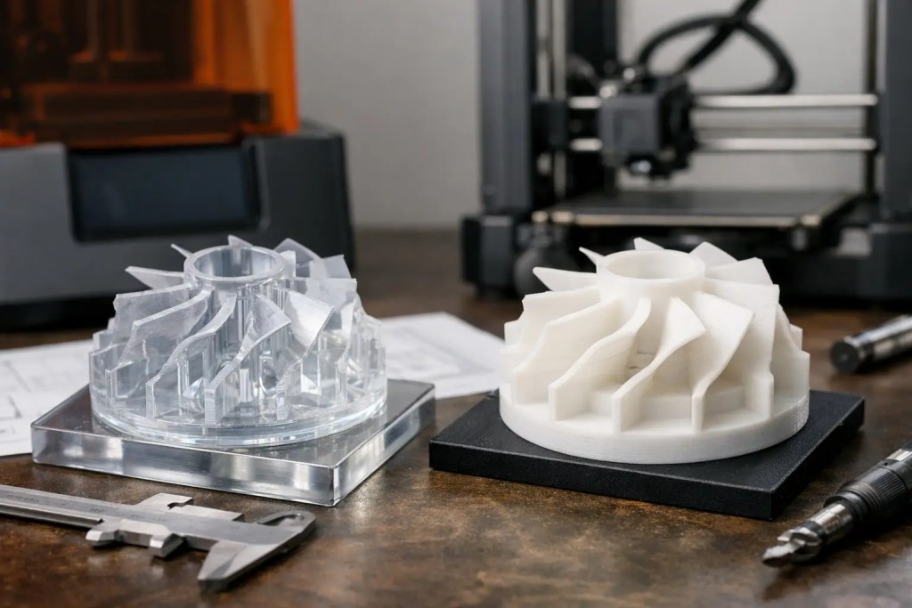
A prototype can pass a visual design review and still fail the test that matters: a snap fit cracks, a bracket creeps under load, or a mating surface will not assemble. The SLA vs FDM prototypes decision is therefore not simply about print quality. It is a process-selection decision that affects dimensional confidence, mechanical behavior, lead time, finishing effort, and the validity of your engineering test.
SLA and FDM are both established additive manufacturing processes, but they build parts from fundamentally different materials and through different mechanisms. SLA cures liquid photopolymer resin with light. FDM deposits melted thermoplastic filament layer by layer. The resulting parts can look similar at a distance, yet their surface quality, isotropy, thermal performance, and failure modes can be very different.
For engineers and product teams, the correct choice starts with the question: what must this prototype prove?
SLA vs FDM Prototypes: Core Process Differences
Stereolithography, or SLA, uses a laser or projected light source to selectively cure a liquid resin. It is known for fine feature reproduction, smooth surfaces, and strong visual presentation. Parts require washing and post-curing after printing, and supports must be removed from the finished surface.
Fused deposition modeling, or FDM, extrudes a heated thermoplastic through a nozzle. It is a practical choice for larger components, functional fixtures, and prototypes that benefit from engineering-grade thermoplastics such as ABS, ASA, PETG, nylon, or polycarbonate. FDM parts also require supports where geometry demands them, but post-processing is generally simpler when a cosmetic finish is not required.
Neither process is universally better. SLA usually wins when detail, surface finish, and tight small-scale geometry are the main priorities. FDM is often the more appropriate option when a part must tolerate handling, elevated temperatures, repeated loading, or a test environment that resembles its eventual use.
| Decision factor | SLA | FDM | | — | — | — | | Surface finish | Smooth, with fine layer visibility | Visible layer lines, dependent on nozzle and layer height | | Fine details | Excellent for small text, thin features, and complex cosmetic geometry | Limited by nozzle diameter and extrusion path | | Material behavior | Photopolymer resin, with properties varying by resin family | Thermoplastic, often closer to production-grade material behavior | | Functional durability | Suitable with engineering resins, but can be brittle depending on material | Often well suited to fixtures and functional test parts | | Large parts | Possible, but resin volume and support strategy affect cost | Generally economical and practical at larger scales | | Finishing | Good starting point for painting, coating, and presentation models | May need sanding, filling, or coating for cosmetic surfaces |
Choose SLA When Appearance and Detail Drive the Test
SLA is the logical starting point for form-and-fit prototypes where visual quality is part of the evaluation. Consumer-product housings, detailed enclosures, fluidic components, miniature features, and presentation models benefit from the process’s smooth surfaces and high feature resolution. It is also effective for checking ergonomic surfaces, parting lines, button placement, and the visual relationship between assembled components.
The advantage is not only aesthetic. Fine surface quality can improve the reliability of certain fit checks. Small locating features, embossed markings, narrow slots, and detailed threads may reproduce more cleanly with SLA than with a standard FDM nozzle. For low-load assemblies, an accurately produced SLA part can provide useful evidence before committing to machining or molding.
However, a smooth SLA part should not be assumed to behave like an injection-molded ABS or polycarbonate component. Standard resins can be relatively stiff and may fracture under impact or flexing. Engineering resin families can improve toughness, heat resistance, or flexibility, but material selection must be matched to the test condition. A tough resin may be suitable for a light-duty enclosure clip, while a high-temperature resin may support a thermal exposure study. Neither automatically replicates the long-term performance of the final production polymer.
Support placement also matters. SLA supports can leave witness marks, especially on cosmetic surfaces and precision mating areas. Orient critical faces to minimize support contact, and identify no-touch surfaces in the CAD review before production. For transparent or translucent parts, post-processing requirements should be defined early because clarity depends on printing orientation, support strategy, sanding, and coating.
Choose FDM When Functional Behavior Matters Most
FDM is frequently the better choice for prototypes that will be installed, handled, loaded, heated, or used on the shop floor. A drill fixture, cable-routing bracket, assembly aid, protective cover, or equipment interface often needs practical toughness more than a showroom finish. In these cases, the availability of thermoplastic materials can make FDM a more representative functional test method.
Material selection remains central. PETG can be useful for general-purpose functional parts with good chemical resistance and toughness. ABS and ASA are common for durable housings, with ASA offering improved UV resistance for outdoor exposure. Nylon supports more demanding wear and fatigue applications, while polycarbonate can provide higher heat resistance and impact performance. Actual performance depends on the specific material, machine capability, print settings, and part geometry.
FDM’s main engineering limitation is anisotropy. Because the part is built from deposited roads of material, strength can differ between the XY plane and the Z direction. A bracket printed upright may split along layer boundaries if the load pulls those layers apart. Reorienting the part so the primary load travels within the layer plane can improve performance substantially, even before material changes are considered.
This is why print orientation should be treated as a design variable, not a production detail. The same applies to wall thickness, fillet size, infill strategy, and the location of holes or threaded inserts. For a fixture that will see repeated clamp loads, a thicker perimeter and correctly oriented layers may matter more than a finer layer height.
FDM surface texture can also affect an assembly test. Layer lines may increase friction in sliding features, reduce sealing performance, or interfere with a close tolerance fit. If the prototype requires smooth sliding contact or a cosmetic exterior, plan for machining, sanding, vapor smoothing where compatible, or a different process.
Accuracy Is About More Than Layer Height
Layer height is often used as a shortcut for accuracy, but it is only one input. A 50-micron SLA layer does not guarantee every dimension will be within 50 microns, and a coarse FDM layer does not make a part unsuitable for dimensional testing. Machine calibration, material shrinkage, orientation, wall geometry, support removal, and post-curing all influence the final result.
SLA generally offers an advantage for fine features and smooth, small-scale geometry. FDM can deliver reliable functional dimensions when tolerances are selected realistically and features are designed for the process. Long, thin walls may distort in either technology. Large flat FDM surfaces can warp as they cool, while SLA parts may change slightly through curing or when unsupported during handling.
For critical interfaces, define the functional requirement rather than relying on a generic tolerance callout. State whether a hole is intended for a clearance fastener, a press-fit insert, a bearing, or a mating printed feature. A hole that must accept a pin at a controlled fit may require intentional oversizing, reaming, or machining after printing. This approach produces better prototypes than attempting to force every feature to final nominal size directly from the printer.
Cost, Lead Time, and Prototype Quantity
For a single small cosmetic part, SLA can be cost-effective because it reduces manual finishing needed to achieve a clean appearance. For larger, more utilitarian parts, FDM often provides a more economical path because thermoplastic feedstock and build strategies are favorable for volume and size.
The calculation changes when several iterations are expected. If the design is still changing weekly, prioritize the process that answers the current technical question at the lowest total iteration cost. An FDM enclosure may quickly validate mounting positions and internal clearance, followed by an SLA version for stakeholder review. Conversely, an SLA prototype may validate a complex fluid path before a tougher FDM part is built for handling trials.
Lead time should include post-processing, not just machine time. SLA requires washing, curing, and support removal. FDM can be ready for basic use soon after printing, although support removal and finishing add time for complex parts. If a part needs tapping, heat-set inserts, painting, sealing, or dimensional finishing, incorporate those operations into the production plan from the start.
A Practical Selection Method for Engineering Teams
Start by identifying the prototype’s primary validation goal: appearance, fit, motion, thermal exposure, load-bearing function, or assembly workflow. Then identify the conditions that could invalidate the result, such as impact, sustained heat, chemical contact, UV exposure, repeated cycling, or a critical mating tolerance.
If the objective is detailed visual assessment or small-feature fit, SLA is usually the stronger first option. If the objective is functional handling, fixtures, durable housings, or thermoplastic-like behavior, FDM deserves priority. Where the project needs both, use each process for the question it answers best rather than asking one prototype to validate every requirement.
At Additive3D Asia, this selection can be reviewed alongside downstream options such as CNC machining, vacuum casting, injection molding, and surface finishing. That broader process view is valuable when the prototype must lead into short-run production rather than remain a one-off model.
The most useful prototype is not necessarily the one with the finest finish or the lowest unit cost. It is the one that produces trustworthy test data quickly enough to support the next engineering decision. Define that decision first, then select SLA, FDM, material, orientation, and finishing around it.