

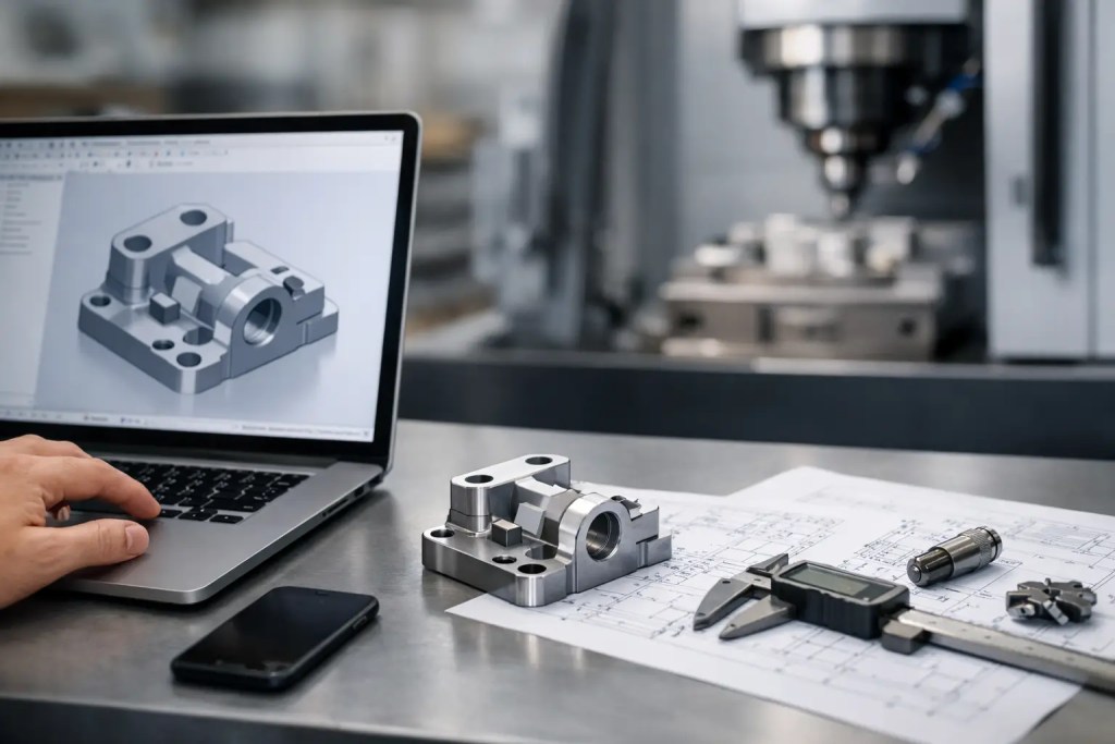
A STEP file that opens correctly in CAD can still create delays on the shop floor if its geometry, units, or design intent are unclear. Knowing how to upload STEP files for manufacturing is not simply a file-transfer task. It is the first quality-control checkpoint between your design team and the process that will produce the part.
For engineers requesting prototypes, fixtures, production aids, or short-run end-use components, a clean STEP upload gives the manufacturing team the information needed to assess geometry, recommend a process, and quote with fewer assumptions. This reduces quotation revisions, prevents avoidable rework, and helps keep the project on schedule.
Why STEP Files Are Preferred for Manufacturing
STEP, typically exported as .step or .stp, is a neutral CAD format designed to exchange solid-model data between software systems. Unlike an STL file, which represents a part as a mesh of triangles, a STEP file preserves boundary-representation geometry. This makes it more useful for manufacturing methods that depend on accurate surfaces, dimensions, holes, radii, and feature relationships.
For CNC machining, sheet metal fabrication, injection molding, and urethane casting, STEP is usually the preferred file format because it allows manufacturing engineers to inspect the solid model directly. It can also support more reliable process planning for additive manufacturing, particularly when orientation, wall thickness, support strategy, and secondary machining must be considered.
STL files remain appropriate for many 3D printing workflows, especially when the mesh has been prepared at sufficient resolution. However, a STEP file is generally the better starting point when the part may move between additive and conventional processes, or when the design requires engineering review before production.
Prepare the CAD Model Before Uploading
The fastest upload workflow starts before you export the file. Review the native CAD model as though another engineer will need to manufacture it without access to your assembly, drawing history, or design rationale.
First, confirm that the model is a valid, watertight solid body. Surface gaps, open shells, self-intersections, and zero-thickness features can cause translation errors or prevent a manufacturing platform from calculating a reliable quote. In most CAD systems, a geometry-check or import-diagnostics tool will identify these issues before export.
Next, verify the unit system. A model designed in millimeters but interpreted as inches can become 25.4 times larger than intended. Most platforms identify units during upload, but the responsibility for confirming scale remains with the design owner. Include dimensions in your drawing or notes for critical components, especially where the part size could be ambiguous.
Remove geometry that does not need to be manufactured. Suppress internal construction bodies, reference components, duplicate solids, and nonfunctional cosmetic details where appropriate. The goal is not to oversimplify the design, but to make the production intent clear. If the uploaded assembly contains multiple components, decide whether they should be quoted as separate parts or produced as a single manufactured unit.
Export Settings That Preserve Design Intent
When exporting, select STEP AP214 or AP242 where your CAD system provides the option. Both are widely used exchange standards and generally preserve solid geometry well. AP242 may also carry product manufacturing information in compatible workflows, but the best choice can depend on the software used by your team and manufacturing partner.
Use a clear file name that identifies the part and revision. A format such as `ProjectName_PartNumber_RevB.step` prevents confusion when several revisions are under review. Avoid names such as `final_final_new.step`, which create unnecessary risk once procurement and production begin.
If your project includes a drawing, inspection criteria, or finishing specification, keep those documents ready for attachment or communicate them in the quotation notes. A 3D model defines geometry, but it does not always communicate tolerances, thread callouts, cosmetic surfaces, or inspection requirements.
How to Upload STEP Files for Manufacturing Platforms
Upload the exported STEP file through the manufacturer’s online quoting system. The platform will typically translate the model, generate a 3D preview, calculate the bounding box, and check for basic issues such as invalid geometry or unsupported dimensions.
Before proceeding, inspect the preview carefully. Confirm that the part is oriented and scaled as expected, all holes and cutouts are present, and no bodies are missing. A successful upload does not automatically mean the model is ready for every manufacturing process. It only confirms that the platform can read the file.
Then enter the production requirements that affect price, lead time, and technical suitability. These typically include quantity, material, manufacturing process, finish, and required delivery date. Where available, select a process based on the part’s function rather than on familiarity with a specific technology.
For example, PA12 made with HP Multi Jet Fusion or SLS is often suitable for functional polymer prototypes, jigs, housings, and low-volume parts requiring good mechanical performance. SLA may be a better fit for fine features and smoother visual surfaces, while FDM can be effective for economical large-format prototypes. Metal SLM with materials such as AlSi10Mg or SS316L may be considered where the application requires metal strength, thermal performance, or corrosion resistance.
A manufacturing partner with both additive and conventional capabilities can assess whether CNC machining, injection molding, vacuum casting, or sheet metal fabrication is the more appropriate route. The correct process depends on tolerances, surface finish, expected load, production volume, and the role of the component in the final assembly.
Add Requirements That Are Not Visible in the Model
A STEP file should be treated as the primary geometric reference, not the complete manufacturing package. Use the order notes or upload supporting documents to identify requirements that a model alone cannot reliably convey.
Specify critical dimensions and tolerances. General tolerances may be adequate for early prototypes, but bearing bores, press-fit features, sealing surfaces, mating interfaces, and alignment features usually need explicit attention. If a feature will be machined after 3D printing, state this clearly so the correct stock allowance and production route can be planned.
Call out threads, inserts, and hardware requirements. Small threaded holes may need tapping, helicoils, heat-set inserts, or other secondary operations depending on the material and process. For polymer additive parts, it is often more reliable to design bosses for inserts than to expect printed threads to handle repeated assembly cycles.
Surface requirements should also be clear. A visual prototype may need sanding, priming, painting, vapor smoothing, or bead blasting. A functional metal component may require machining on selected faces, deburring, polishing, or coating. These decisions affect cost and lead time, but they also determine whether the delivered part is ready for testing or assembly.
Review Manufacturability Feedback Before Approval
Instant quoting accelerates procurement, but it should not replace engineering judgment. Review the platform feedback and any recommendations from the manufacturing team before releasing the order. Pay close attention to thin walls, enclosed cavities, unsupported overhangs, sharp internal corners, and features that may distort during printing or machining.
For additive manufacturing, orientation is a production decision. It can affect surface quality, dimensional accuracy, strength direction, support marks, and cost. A part may be printable in several orientations, but the best orientation depends on which faces are cosmetic, which features are critical, and where mechanical loads will act.
For CNC machining, consider tool access and internal radii. A sharp internal corner in the CAD model cannot be produced with a standard round cutting tool without a relief feature or a smaller tool, which may add cycle time. For molding, draft angles, wall uniformity, undercuts, and gate location can determine whether a design is practical at the required volume.
If the design has high-risk features, include the intended application in the notes. Stating that a part is a low-load fit-check prototype is different from stating that it is a pressure-bearing component or a fixture used in a repetitive assembly operation. Context allows the manufacturing engineer to recommend a more appropriate material, process, or finishing route.
Avoid the Upload Errors That Delay Production
Most upload delays come from a small number of preventable issues. Incomplete solids and incorrect units are common, but revision control can be just as damaging. Ensure the file name, purchase order, drawing revision, and quoted configuration all refer to the same version of the part.
Another frequent issue is assuming that all visible CAD features should be manufactured exactly as modeled. Very small embossed text, fragile snap features, deep narrow channels, and unsupported thin sections may require redesign or a different process. The most efficient approach is to identify critical functional requirements first, then allow noncritical details to be adjusted for manufacturability if needed.
It is also worth separating prototype intent from production intent. A single STEP model can support both, but the selected material, finish, tolerance plan, and inspection requirements may change as the design advances. Uploading the same geometry for a new phase should trigger a fresh review rather than an automatic repeat order.
At Additive3D Asia, the upload-and-quote stage is designed to move projects quickly while retaining the engineering review needed for industrial-grade output. Providing a clean STEP file, complete requirements, and clear revision control gives the production team a reliable basis for selecting the right path from prototype through short-run manufacturing.
A well-prepared upload does more than produce a faster quote. It creates a shared technical record for everyone responsible for the part, making the next decision – material selection, process approval, or production release – easier to make with confidence.