

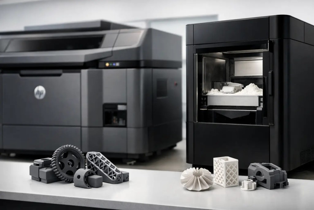
A search for hp multijet fusion vs formlabs x1 sls usually signals a production decision, not simple curiosity. The engineer may need functional nylon parts next week, while procurement needs a process that can be repeated across prototype builds and low-volume orders. In that situation, machine category, material behavior, post-processing requirements, and part volume matter more than headline print resolution.
There is also a naming issue worth resolving before comparing specifications. HP Multi Jet Fusion, commonly called MJF, is a powder-bed polymer production process. Formlabs’ better-known SLS platform has been the Fuse family. If “X1 SLS” is a supplier-specific configuration, a new product designation, or an internal equipment reference, verify the exact machine, material, and post-processing package quoted. The correct comparison is still clear: HP MJF is generally selected for higher-throughput industrial nylon production, while compact SLS systems are often evaluated for accessible in-house powder-bed manufacturing.
HP Multi Jet Fusion vs Formlabs X1 SLS: Core Process Differences
Both technologies produce unsupported polymer parts from a heated powder bed. This gives them a meaningful advantage over filament-based printing when making complex geometries, nested assemblies, internal channels, and multiple parts in one build. Loose powder supports the part during fabrication, so support structures are not typically required.
The processes differ in how they fuse each layer. HP MJF selectively applies fusing and detailing agents to polymer powder, then uses thermal energy to fuse the defined geometry. The process is engineered around densely packed builds, repeatable production workflows, and industrial throughput.
Selective laser sintering uses a laser to scan and sinter each cross-section of the part. In a compact SLS system, the workflow can reduce the barrier to bringing nylon printing closer to an engineering team. However, the rate at which a laser scans the build area, along with chamber capacity and thermal cycle time, can make a significant difference when part quantities increase.
Neither process should be assessed on printer speed alone. A part is not available when the final layer is printed. Cooling, depowdering, media blasting, inspection, dyeing or coating, and shipment all contribute to usable lead time. For a production requirement, evaluate the full manufacturing cycle and not only the machine’s advertised build rate.
Throughput and Part Economics
HP MJF is typically the stronger option when a project requires many parts per build or recurring short runs. Its production value comes from packing the build volume efficiently and producing numerous components within a controlled process. This can lower the unit cost of brackets, enclosures, ducting, clips, jigs, and functional end-use components once the order quantity rises.
A compact Formlabs SLS setup can be a sensible fit for lower-volume internal work, particularly when teams value direct access to a powder-bed process and can plan around its build and cooling schedule. It may suit iterations, fixtures, and limited runs where batch size is modest and the organization has staff trained to manage powder handling and post-processing.
The economics shift with geometry. Ten small parts that nest efficiently may be inexpensive in either process. A large, thick-walled housing that occupies most of the chamber can have a different cost profile, especially if it drives a long cooling cycle. Part orientation, packing density, and thermal mass should be reviewed before using a per-part estimate to choose a technology.
For outsourced manufacturing, MJF is often preferred when the requirement includes repeat batches, predictable production capacity, and a defined path from prototype to short-run supply. For internal printing, the cost model must also include operator time, powder refresh procedures, consumables, equipment maintenance, quality checks, and the space needed for safe powder processing.
Materials and Mechanical Performance
Material selection should lead the conversation. HP MJF is widely associated with production-grade nylon materials, including PA12 and PA11 options. PA12 is commonly specified for balanced strength, stiffness, chemical resistance, and dimensional stability. It is a practical choice for many functional prototypes and production components. PA11 provides greater ductility and impact resistance, which can benefit clips, snap fits, and parts expected to flex repeatedly.
Formlabs SLS materials should be assessed by the specific powder available for the system under consideration. The nominal material name alone does not establish equivalent performance. A PA12 part made on one platform may differ from another in density, isotropy, surface condition, dimensional behavior, and test-data basis. Request material data for the actual process, then assess it against the design load case.
For both processes, nylon is hygroscopic. Parts can absorb moisture from their environment, affecting mass and some mechanical behavior. Applications involving electrical enclosures, fluid exposure, outdoor conditions, elevated temperatures, or regulated documentation need an engineering review beyond a general statement that the material is “nylon.”
If the design requires metal-level stiffness, high continuous-use temperature, flame performance, or a certified resin formulation, neither standard nylon powder process may be the final answer. CNC machining, metal additive manufacturing, injection molding, or another polymer process may provide a better production route.
Surface Finish, Detail, and Tolerances
MJF parts generally leave the build in a gray finish with a fine, slightly textured surface. They can be bead blasted, dyed black, coated, vapor smoothed where appropriate, or otherwise finished according to cosmetic and functional needs. SLS parts also have a powder-bed texture, and their final appearance depends heavily on depowdering and finishing discipline.
Do not choose either process expecting the glossy appearance of a clear SLA prototype. Powder-bed nylon is designed for functional performance and complex geometry, not for transparent surfaces or ultra-smooth cosmetic faces directly from the machine. If appearance matters, specify the required finish at quotation stage. A dyed black prototype, a painted customer-facing enclosure, and an uncoated fixture have different preparation and inspection requirements.
Accuracy should be treated as a production tolerance discussion, not a single number from a brochure. Feature size, wall thickness, orientation, material shrinkage, chamber loading, and post-processing all affect the finished dimension. Critical holes often need to be designed for drilling, reaming, tapping, or the insertion of threaded hardware after printing. Mating surfaces may require machining when the assembly has a tight tolerance stack.
A reliable workflow begins with the CAD model and the function of each critical feature. Identify datum surfaces, fits, threads, sealing interfaces, and cosmetic zones before production begins. This allows the manufacturing team to recommend orientation, allowances, and finishing methods that match the intended use.
Which Process Fits Your Program?
Choose HP MJF when production throughput, repeatable nylon part supply, and efficient nesting are primary requirements. It is especially well suited to functional prototypes moving into short-run production, where the same part must be made repeatedly without redesigning for a fundamentally different process.
Consider a compact Formlabs SLS platform when the priority is bringing powder-bed nylon capability in-house for controlled, lower-volume work. It can give engineering teams faster access to functional parts, provided they have the operational capacity to manage powder, thermal cycles, finishing, and process validation.
The decision becomes less binary when a project has several part types. A low-volume ergonomic model may be better in SLA. A high-detail visual prototype may need a different finish route. A tight-tolerance aluminum fixture may require CNC machining. The strongest manufacturing plan assigns each component to the process that best meets its performance, lead-time, and cost requirements rather than forcing every part through one machine.
Specify the Production Requirement Before Requesting a Quote
A useful RFQ includes the 3D file, quantity, target material, color or finish, critical dimensions, assembly requirements, and delivery date. Add environmental and mechanical requirements when they affect material selection. For example, state whether a snap fit must survive repeated use, whether a housing sees outdoor UV exposure, or whether a fixture needs threaded inserts.
This information makes it possible to compare HP MJF and an SLS alternative on finished-part outcomes rather than assumptions. It also prevents a common procurement problem: receiving an attractive initial price for an unfinished part that later requires additional machining, coating, or inspection.
At Additive3D Asia, the practical objective is not to promote a process by default. It is to manufacture the part that performs as required, with a controlled workflow from CAD review through post-processing and shipment. Start with the load case, critical dimensions, required quantity, and delivery target. The right process usually becomes apparent once those production constraints are defined.