

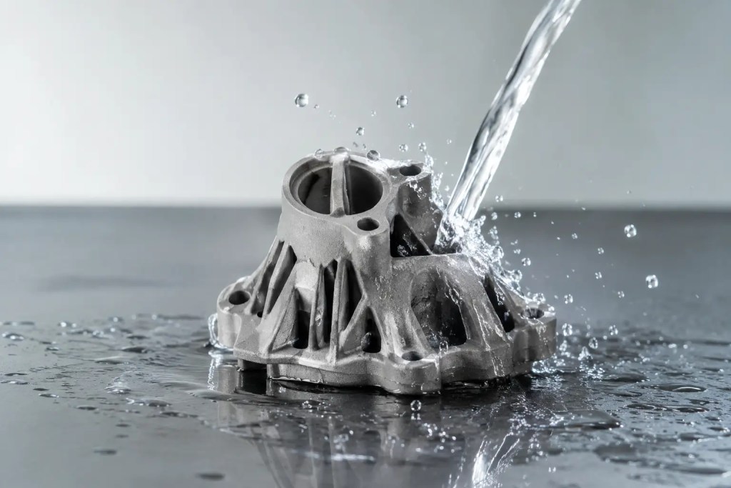
A housing can look fully solid, pass an initial fit check, and still weep fluid through its walls under pressure. That is why the question, is MJF waterproof, cannot be answered with a simple yes or no. Multi Jet Fusion can produce parts suitable for wet environments and fluid-contact applications, but reliable watertight performance depends on the material, geometry, operating conditions, and finishing process.
For engineers specifying an MJF part, the practical distinction is between a part that survives occasional splashes and a part that consistently contains water, coolant, air, or another medium at a defined pressure. Those are different requirements and should be documented differently.
Is MJF Waterproof in Its As-Printed State?
MJF parts are not automatically waterproof in every application. The process fuses polymer powder layer by layer, producing strong, functional components with good isotropic mechanical performance. However, the as-printed surface can retain a fine texture and microscopic porosity. Under immersion, cyclic pressure, or extended fluid exposure, those pathways may permit leakage.
PA12 is the most common MJF material for functional polymer parts. It has low moisture absorption relative to many other nylon materials, good chemical resistance, and stable mechanical properties. These characteristics make it a sound starting point for enclosures, ducts, brackets, manifolds, and fluid-adjacent assemblies. Still, low moisture absorption is not the same as a validated waterproof seal.
An as-printed PA12 component may be adequate for a splash-resistant cover, a protected electronics enclosure with a gasketed lid, or a low-demand water-contact application. It is less appropriate to assume that an untreated part will reliably contain pressurized liquid or air. Where leakage would cause product failure, every part should be treated as a performance-critical component requiring a defined sealing and test plan.
Waterproof, Water-Resistant, and Watertight Are Different Requirements
The term waterproof is often used too broadly during design reviews. For production decisions, it helps to separate the requirement into three levels.
A water-resistant part can tolerate incidental moisture, splashes, or short exposure. A waterproof part is expected to prevent water ingress under stated conditions, such as immersion depth and duration. A watertight part is designed to prevent fluid leakage from within the component, often with an associated pressure rating or leak-test criterion.
For example, an MJF enclosure may need to meet an ingress-protection target when assembled with gaskets, fasteners, and cable interfaces. In that case, the printed shell is only one element of the sealing system. A printed reservoir, pump component, or pneumatic manifold has a different responsibility: its walls and internal channels must resist permeation and leakage from the inside.
The operating environment also changes the answer. Room-temperature water at low pressure is relatively forgiving. Hot water, coolant, fuel, cleaning chemicals, saltwater, vacuum, compressed air, and repeated pressure cycles require more careful material and finishing selection. Chemical compatibility and seal durability must be evaluated together.
Why MJF Parts Can Leak
Leakage is rarely caused by one factor alone. It usually results from the interaction between process conditions, part geometry, and service conditions.
First, surface porosity can create microscopic flow paths. These may be insignificant for a dry assembly but become visible when a part is submerged or subjected to pressure. Internal channels are especially difficult because their surfaces cannot always be reached evenly by secondary finishing processes.
Second, thin walls increase risk. A thin wall has less material through which to resist permeation and may flex under pressure. Flexing can open microvoids or stress transitions near ribs, bosses, threads, and sharp internal corners. A thicker wall is not a universal fix, but it generally provides a better margin for sealed applications.
Third, geometry affects powder removal and finishing access. Deep channels, blind cavities, and complex manifold passages may retain unfused powder. If a coating or infiltration process cannot reach all wetted surfaces, the part may be sealed externally while leakage remains inside the flow path.
Finally, assembly interfaces often fail before the printed material does. Threaded ports, press-fit inserts, gasket grooves, and bonded joints require standard sealing practices. O-rings need controlled gland geometry. Threads may require sealant or a dedicated face seal. A carefully sealed MJF wall will not compensate for an uncontrolled interface.
Material Selection for Wet Applications
PA12 is usually the preferred baseline material for MJF parts exposed to water because of its low water uptake and favorable balance of strength, toughness, and chemical resistance. It is widely used for functional prototypes, jigs, fixtures, enclosures, and short-run end-use parts.
PA11 can be a better option where ductility and impact resistance are priorities. Its behavior under moisture and chemical exposure must still be evaluated against the actual operating environment. Material selection should not be based only on a generic water-resistance statement. Temperature, pressure, fluid chemistry, UV exposure, cleaning methods, and expected service life all affect the correct choice.
For aggressive fluid exposure or high-pressure duty, polymer MJF may not be the right final process. CNC-machined engineering plastics, metal additive manufacturing, or conventional metal fabrication may provide a more direct path to the required performance. The correct process is the one that meets the specification repeatably, not simply the one that produces the most complex geometry.
How to Make MJF Parts Watertight
For demanding applications, post-processing is typically the most reliable route to watertight MJF parts. The best method depends on where the surfaces are located, the required finish, dimensional tolerances, and the medium being contained.
Chemical or vapor smoothing can reduce surface roughness and close superficial porosity. It is effective for many external surfaces and can improve cleanability as well as sealing behavior. Engineers should account for potential dimensional changes, particularly on small holes, snap features, fine threads, and precision mating surfaces.
Coatings provide another route. Polyurethane, epoxy, and specialized sealant systems can form a barrier layer over the printed surface. Coating selection must consider adhesion, film thickness, flexibility, chemical resistance, and coverage of complex areas. A coating that performs well in static water may not withstand thermal cycling or a solvent-based fluid.
Infiltration can penetrate surface-connected pores and improve leak resistance. This approach can be useful for parts with accessible surfaces, but process control matters. Inconsistent penetration, trapped material in narrow passages, or insufficient cure time can create variable results.
For sealed assemblies, design the interfaces around standard sealing features rather than relying on flat printed faces alone. O-ring grooves, captive gaskets, compression limits, and machined sealing lands can materially improve repeatability. Hybrid manufacturing is often efficient here: use MJF for the complex body, then machine critical ports, bores, and gasket surfaces to tolerance.
Design Rules That Reduce Leakage Risk
A watertight requirement should be identified before the part is quoted and built. Retrofitting a seal strategy after a leak test often adds time and creates unnecessary design iterations.
Use wall thickness appropriate to pressure, part size, and allowable deflection. Avoid abrupt thickness changes around fluid channels, and reinforce ports or fittings that will see torque or hose loads. Where possible, keep wetted passages accessible for powder removal and finishing. Include drain or escape provisions only where they will not compromise the sealed volume in service.
Specify the actual requirement rather than stating waterproof. Define the fluid, temperature range, pressure or vacuum level, exposure duration, number of cycles, and permitted leak rate. If the part is an enclosure, specify the assembled ingress target and identify every interface that contributes to sealing performance.
A prototype should then be tested under representative conditions. A simple immersion test may reveal gross leakage, but it does not replace pressure testing, vacuum decay testing, or repeated thermal and pressure cycling where the product will experience those loads. Validation should reflect the failure mode that matters to the final application.
Production Control Matters as Much as the Finish
A one-off part can pass a test by chance. Production parts need a controlled process. Build orientation, material handling, powder refresh strategy, post-processing parameters, coating cure conditions, and inspection criteria can all influence watertight performance.
For short-run and end-use production, define acceptance criteria before manufacturing begins. This may include visual inspection, dimensional checks at sealing interfaces, a documented leak-test method, and part traceability. If a coating or smoothing operation is used, retain process records that connect the finished part to the required treatment.
At Additive3D Asia, this type of requirement is best addressed at the quoting stage, when the engineering team can assess material choice, geometry, post-processing access, and the need for secondary machining. Early review reduces the risk of selecting MJF for a duty cycle that requires a different material or manufacturing route.
The most useful next step is to turn the word waterproof into a measurable specification. Once the fluid, pressure, temperature, life target, and allowable leak rate are clear, a manufacturing process can be selected and validated with confidence.