

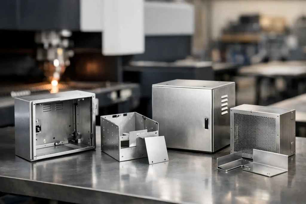
A controller enclosure can look correct in CAD and still fail at the brake press. A flange may be too short for the selected tooling, a connector cutout may sit too close to a bend, or a heavy internal component may distort a thin mounting panel. Sheet metal prototypes for industrial enclosures expose these production issues before they become expensive changes in a production release.
For engineers building electrical cabinets, machine guards, test equipment housings, communications hardware, or industrial control units, the prototype is more than a visual model. It is a functional check of fit, access, thermal performance, assembly sequence, grounding strategy, and manufacturing feasibility. The most useful prototype program treats fabrication as an engineering validation stage, not a final cosmetic exercise.
What an Enclosure Prototype Must Prove
An industrial enclosure is a system of interfaces. It must locate PCBs, power supplies, terminal blocks, fans, cable glands, displays, handles, fasteners, and mounting hardware while protecting the equipment inside. The prototype should verify the interfaces that are most costly to alter after production starts.
Start with the installation environment. An indoor benchtop instrument has different requirements from an enclosure mounted on a production line, outdoor cabinet, or mobile machine. Exposure to heat, moisture, vibration, dust, chemicals, and electromagnetic interference influences material selection, seam design, coating, and the level of sealing required.
The next priority is assembly. Check whether technicians can install components and drive fasteners without blocked access. Confirm that cable bend radii are achievable, removable panels clear internal hardware, and serviceable parts can be replaced without dismantling the whole unit. A prototype also helps identify whether assembly requires tabs, captive hardware, PEM fasteners, hinges, or separate brackets.
Functional validation should include real hardware wherever possible. A representative PCB is helpful, but actual connectors, harnesses, cooling fans, and power components reveal tolerance stack-up and clearance problems that simplified models can hide. For heat-generating assemblies, the prototype can also validate vent placement, fan orientation, and the available space around airflow paths.
Design Rules for Sheet Metal Prototypes for Industrial Enclosures
Prototype lead time is improved when the CAD model follows practical sheet metal rules from the outset. The specific limits depend on material, thickness, press brake tooling, and part geometry, but several decisions consistently affect manufacturability.
Keep bends and features manufacturable
Use a consistent material thickness within each part where possible. Mixed thicknesses can be necessary, especially for large equipment cabinets or reinforced mounting areas, but they add fabrication complexity. For a first prototype, separate a thick reinforcement plate from a thinner outer cover when that preserves standard bend operations.
Bend radius should suit the selected material and thickness. Tighter bends are not always better. They can increase cracking risk, alter finished dimensions, and require specialized tooling. For many enclosure designs, a bend radius near the material thickness is a practical starting point, followed by review against the actual material condition and fabrication process.
Keep cutouts, holes, and slots clear of bend lines. Features too close to a bend can deform, become elongated, or interfere with tooling. Where the position cannot change, it may be necessary to modify the bend sequence, add a relief feature, or redesign the component interface.
Bend reliefs also deserve attention. At the end of a flange, a properly sized relief helps prevent tearing and uncontrolled material deformation. Small details like this are easy to miss in a CAD review but directly influence whether a flat pattern can be formed consistently.
Design around real fasteners and components
Specify hardware early. A mounting hole pattern depends on the actual standoff, screw head, nut, or self-clinching fastener being used. Avoid assigning generic holes and assuming the production team can resolve the hardware later. The correct hole diameter, edge distance, and installation sequence should be established during the prototype stage.
For access panels, confirm the difference between a fastener that secures the panel and one that can be installed in the available space. A screwdriver may need vertical clearance that the enclosure interior does not provide. Captive screws, quarter-turn latches, or a redesigned flange can solve the problem, but only when the constraint is recognized before release.
Account for tolerance stack-up
Sheet metal dimensions are affected by cutting accuracy, bend angle variation, bend deduction, hardware installation, and coating thickness. A single dimension may be well controlled while the assembled relationship between several bent features moves enough to affect a PCB, door, or connector.
Critical interfaces should be dimensioned from stable datums. For example, connector cutouts and board mounting locations may need to reference the same formed face rather than separate flanges. Where alignment is highly sensitive, use locating features such as tabs, slots, dowel positions, or dedicated brackets instead of relying on accumulated bend dimensions.
Do not apply tight tolerances uniformly. Identify the features that control electrical clearance, connector alignment, mating panels, or mounted equipment, then specify appropriate requirements for those areas. This keeps the prototype commercially practical while concentrating inspection effort where it matters.
Select Material by Operating Requirement
Material selection should reflect the enclosure’s mechanical and operating environment, not only the desired appearance. Cold-rolled steel is often selected for cost-effective indoor industrial cabinets, good stiffness, and compatibility with powder coating. It is a practical choice when corrosion resistance comes primarily from the finishing system.
Stainless steel, including grades such as SS304 or SS316L, is appropriate where corrosion resistance, washdown exposure, or hygienic operation is a major requirement. SS316L offers stronger resistance in demanding chemical or marine-adjacent environments, but it costs more and may require different fabrication considerations than mild steel.
Aluminum is useful where weight reduction, natural corrosion resistance, and thermal conductivity are priorities. Grades such as 5052 are commonly suited to formed enclosure work, while the final selection depends on stiffness, bendability, finish, and weld requirements. Aluminum can be an effective choice for portable instruments and thermal management housings, although thin panels may require ribs, hems, or brackets to achieve the required rigidity.
Material thickness is a trade-off. Increasing thickness improves stiffness and thread engagement potential, but it adds weight, cost, and bending force. Large flat panels may benefit more from formed returns, ribs, or strategically placed internal supports than from increasing the thickness across the entire enclosure.
Use Finishing as a Functional Specification
A finish is not simply a color decision. Powder coating provides a durable coating for many industrial applications and can improve appearance, corrosion resistance, and handling durability. The coating must be considered in fits between mating panels, around grounding points, and at tight holes or slots.
For aluminum, anodizing can provide corrosion resistance and a controlled appearance while retaining a metallic surface. Brushed or bead-blasted finishes may suit visible equipment panels, but surface preparation should be selected with the operating environment in mind. A cosmetic finish that shows fingerprints or scratches easily may not be appropriate for frequently serviced equipment.
Electrical grounding requires explicit planning. Paint and powder coat are insulating layers, so ground paths may require masked areas, serrated washers, grounding studs, conductive gaskets, or designated bonding points. A prototype is the right time to verify continuity with the actual fasteners and assembly sequence.
If the enclosure needs ingress protection or electromagnetic shielding, prototype seams, gasket compression, overlaps, and cable entry points. These requirements often change panel geometry and hardware choices. A standard folded cover may be adequate for one application, while a sealed outdoor design may need welded seams, compression latches, and purpose-designed gasket channels.
Build a Prototype Plan That Leads to Production
The best prototype does not attempt to validate every question at once. Define the decision each build must support. An early unit may validate overall form, internal packaging, and assembly access. A later unit may use production-intent material, hardware, coating, and sealing features to validate performance and the manufacturing process.
Provide a clean manufacturing package. A STEP file is typically preferred for 3D geometry, supported by a 2D drawing when critical tolerances, bend notes, finish requirements, hardware specifications, or inspection requirements need to be communicated. Clearly identify cosmetic surfaces, revision level, material, thickness, grain direction when relevant, and any protected or masked areas.
Manufacturability feedback should be reviewed before cutting begins. This is where an experienced fabrication partner can flag inaccessible bends, impractical hems, inconsistent feature spacing, or hardware conflicts. Resolving those items in CAD is faster than correcting them after formed parts arrive.
At Additive3D Asia, sheet metal fabrication can be supported alongside CNC machining, additive manufacturing, laser cutting, and post-processing. That broader capability is useful when an enclosure prototype includes machined heat sinks, printed cable guides, custom brackets, or low-volume functional components that must be tested as one assembly.
Evaluate the Finished Enclosure Under Real Conditions
Inspection should go beyond checking the overall length, width, and height. Assemble the enclosure using the intended work instructions and document where technicians slow down, force parts into position, or need an extra tool. Those observations often identify the changes that most improve repeatability in short-run production.
Test door swing, panel removal, connector engagement, cable routing, fan operation, grounding continuity, and wall or rack mounting. Where relevant, run vibration, thermal, spray, or dust tests using a production-representative build. Record any issue against a defined datum and revision so the next CAD update is unambiguous.
A well-executed sheet metal prototype turns enclosure development from a drawing review into a controlled manufacturing decision. Build it early enough to change the design, specify the interfaces that govern performance, and use the findings to release a part that can be fabricated repeatedly, not just once.