

A bracket that looks simple in CAD can become expensive fast if the process does not match the part. This is usually the real question behind when to use sheet metal: not whether metal will work, but whether sheet metal is the most efficient path for strength, repeatability, cost, and lead time.
For engineers and sourcing teams, sheet metal sits in a practical middle ground. It is faster and more economical than machining for many flat or folded geometries, and more production-ready than additive for parts that need established metal grades, familiar finishing routes, and scalable fabrication. The right choice depends on geometry, volume, tolerances, cosmetic requirements, and how the part will actually be assembled and used.
When to use sheet metal
Sheet metal is the right fit when your part starts as a flat profile and gains function through cutting, bending, punching, or simple forming. If the geometry can be produced from a metal sheet without removing large amounts of material, the process is usually efficient.
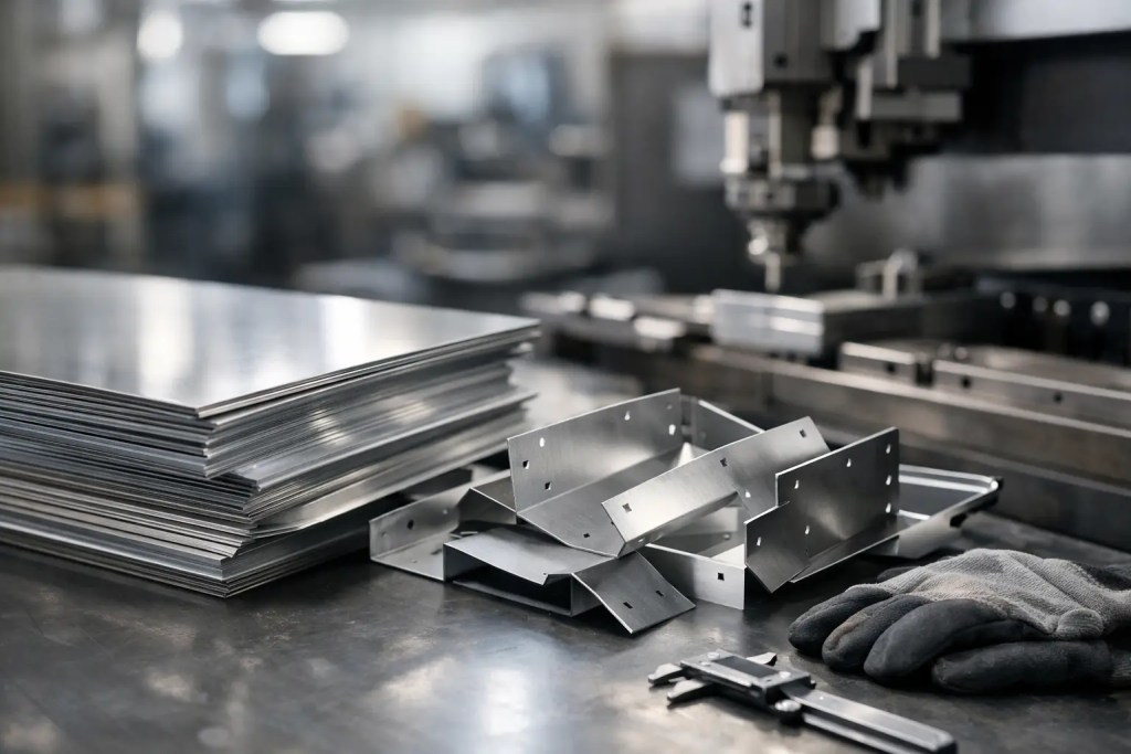
This makes sheet metal a strong option for covers, housings, brackets, panels, trays, clips, electrical enclosures, machine guards, and support structures. These parts often need a predictable balance of stiffness, weight, and cost. They also benefit from standard fabrication steps that are well understood across industries, from electronics and industrial equipment to medical devices and automation systems.
The process becomes especially attractive when you need multiple units with consistent dimensions. Once a design is validated for manufacturability, fabrication is repeatable and procurement is straightforward. For teams moving from prototype to short-run production, that repeatability matters as much as unit cost.
Where sheet metal performs best
The biggest strength of sheet metal is structural efficiency. A thin metal wall with the right bend geometry can deliver substantial stiffness without the weight or cost of a thicker machined block. Features like flanges, hems, ribs, and returns add rigidity in ways that are difficult to match economically with other processes.
This is why sheet metal is commonly selected for enclosures and support components. A folded enclosure can protect internal electronics, provide mounting points, support thermal management, and maintain a professional finished appearance. A bracket can be cut and bent from a single blank rather than machined from solid stock or assembled from multiple pieces.
Sheet metal also makes sense when material familiarity is important. Teams often specify aluminum, stainless steel, or mild steel because they need known performance in corrosion resistance, weldability, conductivity, or load-bearing behavior. In regulated or qualification-heavy environments, using conventional metals and standard fabrication routes can simplify downstream validation.
Another advantage is finishing flexibility. Powder coating, plating, brushing, bead blasting, silk screening, and laser marking are all compatible with common sheet metal workflows. If a part must meet both functional and cosmetic requirements, sheet metal is often easier to finish consistently than many prototype-only processes.
Common use cases
Electrical cabinets, server chassis, battery housings, mounting plates, HVAC components, retail fixtures, control box covers, and machine panels are obvious examples. Less obvious but equally common applications include test fixtures, equipment guards, assembly aids, and custom integration hardware for pilot production.
In these cases, the design intent aligns well with fabrication methods. The part geometry is not fighting the process. That alignment is what keeps cost and turnaround under control.
When sheet metal is better than machining
Machining is the right answer when a part needs complex 3D geometry, tight internal features, deep pockets, or precision across multiple axes. But if the design is mostly flat faces, holes, slots, and bends, machining may be unnecessary.
A machined bracket made from billet removes material to create shape. A sheet metal bracket starts with shape already embedded in the raw material and uses cutting and bending to realize it. That difference affects both waste and cycle time.
For medium-size components, sheet metal is often more economical than CNC machining because material utilization is better and fabrication time is lower. The trade-off is geometric freedom. You gain efficiency, but only if the design follows bend rules, relief requirements, and access constraints.
Tolerance expectations also need to be realistic. CNC machining generally supports tighter precision on highly critical features. Sheet metal can hold good functional tolerances, but bend variation, springback, and feature placement relative to formed edges must be accounted for in the design.
When sheet metal is better than 3D printing
Additive manufacturing is excellent for complex geometry, internal channels, low-volume customization, and fast iteration. It reduces tooling constraints and can compress development cycles. But once a part settles into a geometry that is fundamentally planar or folded, sheet metal often becomes the stronger production choice.
This shift usually happens when teams need higher throughput, lower unit cost at quantity, familiar metal properties, or easier integration with standard fastening and finishing methods. A 3D printed metal or polymer enclosure may be useful in concept validation, but a laser-cut and bent metal enclosure is often more practical for field use and repeat builds.
There is also a scale effect. For one or two units, additive can avoid setup overhead and support design changes quickly. For tens or hundreds of units, sheet metal frequently becomes more competitive, especially when the design does not require additive-only geometry.
An engineering-first workflow often uses both. Early prototypes may be 3D printed to validate fit and assembly, then shifted to sheet metal once mounting locations, cable routing, access panels, and wall thickness are finalized. That is not a compromise. It is process selection based on lifecycle stage.
Design signals that point to sheet metal
If your model can be unfolded into a flat pattern with a manageable number of bends, that is a strong indicator. Uniform wall thickness is another. So is a design that relies on tabs, slots, louvers, simple embosses, or PEM hardware rather than deeply contoured surfaces.
Assembly requirements matter too. Sheet metal is often the right answer when the part needs threaded inserts, spot welding, hinges, captive hardware, or straightforward attachment to frames and panels. These are mature production methods with predictable outcomes.
Material thickness should match the application rather than personal preference. Overdesign adds cost and forming difficulty. Underdesign creates flex, distortion, or field failures. In practice, the best results come from selecting thickness based on load, span, fastening strategy, and finish requirements, then refining geometry to add stiffness where needed.
Constraints to watch early
The most common issues are bend radii that are too tight, holes too close to bends, inaccessible features for tooling, and part dimensions that exceed machine limits. Cosmetic surfaces can also drive design choices, since tool marks, weld locations, and grain direction may matter on visible faces.
If a part needs extremely complex compound curves, organic surfaces, or hidden internal channels, sheet metal is usually the wrong process. If it needs only a few precise bends and standard cut features, it is usually the right one.
Cost, volume, and lead time trade-offs
Sheet metal economics improve when parts are repeated. For prototypes and low-volume production, laser cutting and CNC bending can still be efficient because they avoid hard tooling. That makes sheet metal viable much earlier than many teams assume.
As volume increases, process planning becomes more valuable. Nesting optimization, fixture strategy, hardware insertion, welding time, and finishing all influence total cost. A part that is cheap to cut but slow to assemble may not be a good design. Cost should be evaluated at the assembly level, not only the flat blank level.
Lead time is usually favorable when the design is manufacturing-ready. Standard materials and finishes move faster than custom specifications. This is one reason engineers increasingly prefer a supplier that can review CAD, flag manufacturability risks early, and support adjacent processes such as CNC machining, laser cutting, and post-processing under one quality system.
At Additive3D Asia, this kind of process selection is part of the value proposition. Not every metal part should be printed, and not every production component should be machined from billet. The decision should follow performance, geometry, quantity, and delivery requirements.
How to decide with confidence
If the part can be made from flat stock, needs metal-grade strength, and is headed toward repeat builds, sheet metal deserves serious consideration. If you are forcing a highly three-dimensional design into a folded part, it probably does not.
The fastest way to make the right call is to evaluate the part against four questions: Can it be flattened logically, will bends create the needed stiffness, are tolerances appropriate for formed metal, and does projected volume justify the workflow? If the answer is yes to most of those, sheet metal is often the most reliable path.
Good manufacturing decisions are rarely about choosing the most advanced process. They are about choosing the process that delivers the required outcome with the least friction. Sheet metal remains one of the most dependable options for exactly that reason.