

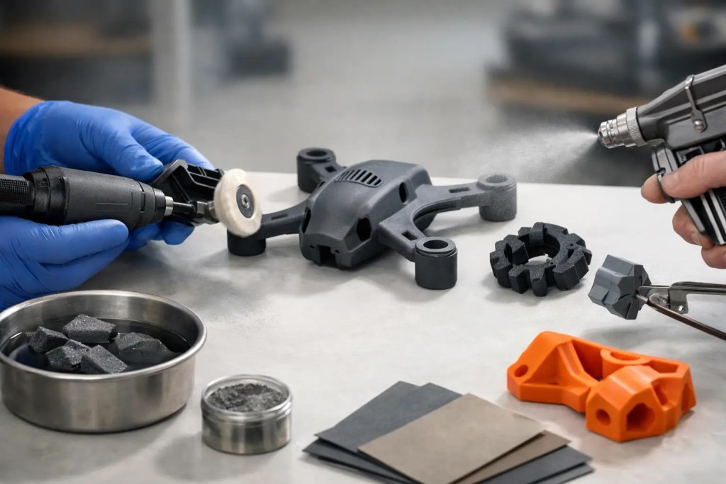
A part can print perfectly and still fail the handoff to testing, assembly, or customer review. In production environments, that gap is usually closed by post-processing. The best post processing methods are not the ones that look impressive on a sample board. They are the ones that match part geometry, material behavior, tolerance targets, and end-use requirements without adding avoidable cost or lead time.
For engineering teams, post-processing is not cosmetic cleanup at the end of the job. It is a controlled manufacturing step that affects fit, surface quality, sealing performance, paint adhesion, and in some cases mechanical reliability. A PA12 housing, an SLA master pattern, and an AlSi10Mg bracket do not need the same finishing path, even if all three require a better surface than the as-built condition.
How to choose the best post processing methods
The right method starts with the part’s job, not the machine that made it. If the part is going into an internal test rig, support removal and light bead blasting may be enough. If it will be customer-facing, painted, or used as a master for molding, the finishing route becomes much more demanding.
Three questions usually narrow the field quickly. First, what surface outcome is required: functional, cosmetic, or near-molded? Second, which dimensions or interfaces must remain tightly controlled after finishing? Third, is the part a one-off prototype or part of a repeatable low-volume workflow? A finish that works on one engineering sample may be a poor choice if it introduces variability across a 200-part batch.
Material and process also matter. MJF and SLS parts often benefit from depowdering, bead blasting, dyeing, and smoothing methods that preserve geometry. SLA parts may need support removal, UV post-cure, sanding, and coating to achieve presentation-grade surfaces. Metal SLM parts often require more intensive steps such as support removal, machining, blasting, polishing, or heat treatment depending on the application.
Best post processing methods by outcome
Support removal and depowdering
This is the baseline step for most additive parts, but it should not be treated as trivial. Poor support removal can gouge surfaces, shift critical edges, or leave witness marks that become obvious after painting. In powder-bed systems, incomplete depowdering can trap media in channels and cavities, creating downstream issues in assembly or field use.
For functional prototypes and many end-use polymer parts, careful support removal followed by controlled media blasting is often the most efficient path. It improves consistency, removes loose residue, and gives the part a cleaner, more uniform appearance without excessive material removal.
Sanding and manual surface refinement
Sanding remains one of the most common post-processing methods because it is flexible and relatively low cost. It works well for removing print lines, smoothing support contact points, and preparing parts for primer or paint. It is especially useful on SLA and FDM parts where layer lines or support marks are visually obvious.
The trade-off is repeatability. Manual sanding depends heavily on operator control, and it can round edges or alter local dimensions if overdone. For appearance models and early prototypes, that may be acceptable. For mating features, sealing faces, or tolerance-sensitive geometries, sanding needs tight process control or should be limited to non-critical surfaces.
Bead blasting
Bead blasting is one of the best post processing methods for powder-bed polymer parts that need a clean, uniform, production-ready finish without major dimensional change. MJF and SLS parts respond particularly well because blasting removes residual powder and reduces the visual roughness of the as-built surface.
It is not a cure-all. Blasting will not eliminate staircase effects on highly contoured faces, and aggressive settings can soften details or thin delicate features. Still, for many jigs, fixtures, enclosures, and functional housings, it offers a strong balance of speed, consistency, and cost.
Tumbling and vibratory finishing
For small parts that need edge softening and a more consistent feel across batches, tumbling can be effective. It is commonly used when parts have many similar features and throughput matters more than preserving every sharp detail. The process can improve touch surfaces and reduce minor surface irregularities.
The limitation is feature control. Thin walls, fine text, and precise corners can be affected. Tumbling is usually better suited to robust geometries than to intricate parts with strict cosmetic requirements.
Chemical smoothing and vapor smoothing
When teams need a sealed surface, lower porosity, and a more injection-molded appearance, chemical smoothing can be a strong option for selected polymer materials. It reduces visible layer texture and can improve cleanability for parts used in fluid handling, consumer-facing housings, or applications where surface friction matters.
This method brings clear benefits, but it also changes the surface more substantially than blasting or light sanding. That means fit features, threads, embossed text, and tolerance-critical faces must be reviewed carefully. The best results come when the part is designed with the finishing step in mind rather than treated after the fact as a visual upgrade.
Priming and painting
If the goal is a customer-ready model, a color-matched prototype, or a display part that approximates final product appearance, priming and painting are often necessary. Primer reveals surface defects that may not be obvious in the raw part, while paint creates the final visual standard.
This route is labor intensive, and quality depends on surface preparation. Painting over an inconsistent substrate usually produces inconsistent results. It also adds thickness, which can affect fit if mask strategies and datum surfaces are not planned in advance. For engineering teams, the key is to separate cosmetic zones from functional interfaces early in the drawing or RFQ stage.
CNC machining after printing
For hybrid workflows, machining is often the most reliable answer when a printed part includes tolerance-critical features. Datum faces, bores, threaded holes, and sealing surfaces may be printed near-net shape and then machined to final specification. This is common for metal additive parts, but it can also apply to selected polymer applications.
Machining adds cost, yet it removes uncertainty. If a bracket needs both lightweight internal geometry and accurate mounting interfaces, additive plus machining is usually a better engineering decision than trying to force a pure-print workflow to meet every requirement.
Heat treatment and stress relief for metal parts
For metal additive manufacturing, post-processing is often structural as well as cosmetic. Stress relief and heat treatment can improve stability, reduce residual stress, and support downstream machining. Depending on the alloy and part function, these steps may be essential rather than optional.
The exact route depends on the material and performance target. AlSi10Mg and SS316L will not follow identical post-build requirements. This is why metal finishing should be specified as part of the production plan, not added after the build is complete.
The best post processing methods for common applications
For functional prototypes, the best choice is usually the simplest method that delivers the required result. Bead blasting, support removal, and selective sanding often get the job done faster than a fully cosmetic workflow. Over-finishing a test part can hide real manufacturing behavior and delay iteration.
For appearance models, a more layered approach makes sense. Sanding, filler or primer, repeated surface inspection, and paint deliver the visual quality needed for stakeholder review, trade show display, or investor presentations. Here, the finish is part of the product story, so cosmetic discipline matters.
For end-use parts, repeatability becomes the deciding factor. A finish that looks excellent on one sample but varies across a production batch is not the best option. Standardized blasting, dyeing, vapor smoothing, machining, or controlled coating systems generally outperform heavily manual finishing when consistency is required.
For tooling, jigs, and fixtures, surface finish should be tied to function. Contact areas, ergonomic grips, wear surfaces, and alignment features deserve attention. Hidden faces usually do not. This is where engineering-first post-processing saves both time and budget.
Where teams usually make the wrong call
The most common mistake is choosing a finish based on appearance alone. A smoother surface can look better but reduce edge definition, alter fit, or create more variation than the application allows. Another frequent issue is treating all printed materials the same. What improves an SLA part may be inefficient or even counterproductive on MJF, SLS, FDM, or SLM components.
The other problem is late-stage decision making. If finishing requirements are only discussed after the part is built, teams lose options. Feature allowances, masking plans, machining stock, and surface callouts should be considered before production begins. That is especially true when multiple technologies are involved in one program.
A capable manufacturing partner should help define that path up front. For companies moving from prototype to short-run production, this is where an engineering-led workflow makes a measurable difference. Additive3D Asia approaches post-processing as part of the full production route, with process selection tied to material, geometry, finish requirement, and delivery target.
The best post processing methods are the ones that move the part closer to real use, not just better photography. When finish decisions are tied to function, tolerance, and repeatability, teams spend less time correcting parts after the fact and more time getting products into testing, assembly, and market.