

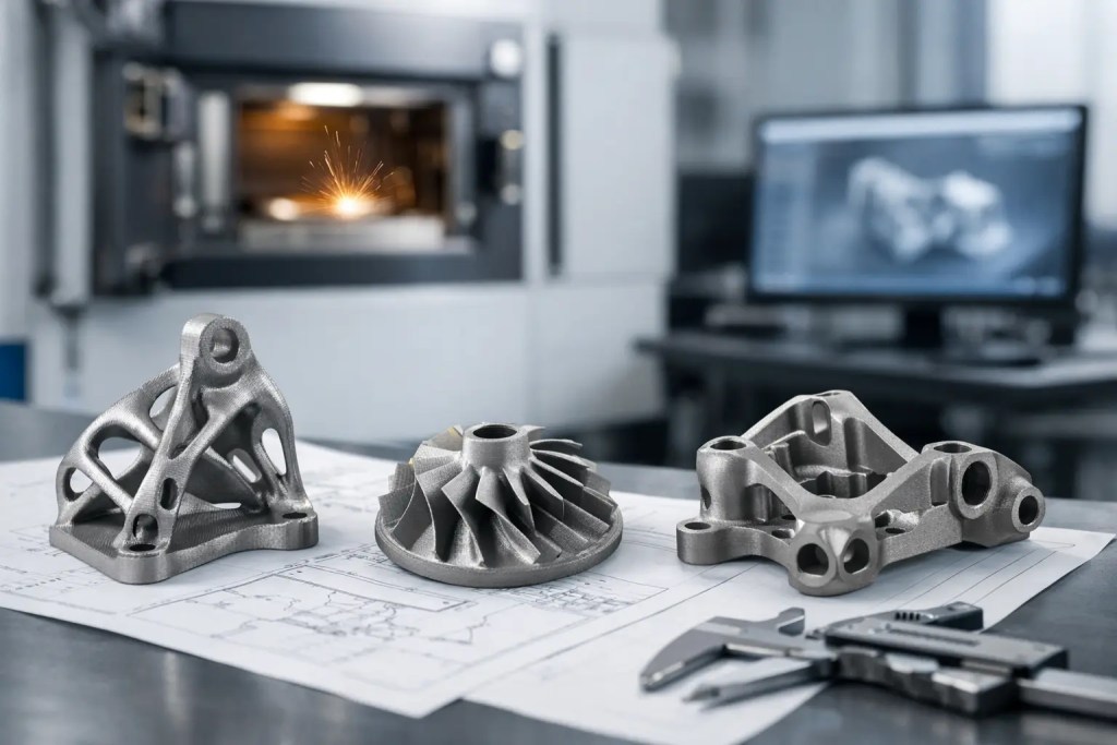
A support structure can consume machine capacity, add post-processing time, and leave witness marks on functional surfaces. That is why engineers ask how to design supportless metal parts for SLM. The practical answer is not to eliminate supports at any cost. It is to design geometry, orientation, and thermal behavior so supports are required only where they protect part quality, build stability, or critical dimensions.
For metal laser powder bed fusion, often referred to as SLM, supports have two jobs: they anchor the part against residual-stress distortion and conduct heat away from newly melted material. A geometry that prints well without supports in AlSi10Mg may still need local support in SS316L, depending on section thickness, build orientation, machine parameters, and the part’s performance requirements. Supportless design is therefore a manufacturability decision, not a styling exercise.
Start With What Supports Are Preventing
Before changing a CAD model, identify why the slicer is proposing support. Down-facing surfaces are the obvious cause, but they are not the only one. Long, thin features can curl as residual stress accumulates. Large cross-sections can retain heat and create distortion. Internal cavities may be printable but impossible to depowder or inspect.
A useful review separates each proposed support zone into one of three conditions: unsupported overhang, thermal risk, or anchoring risk. An unsupported overhang may be solved by changing an angle or replacing a flat surface with a self-supporting profile. Thermal and anchoring risks may require a different orientation, a revised section thickness, or targeted supports that are easy to remove.
This distinction prevents an expensive mistake: removing supports that appear unnecessary in CAD but are required to keep the build attached to the plate and within tolerance.
How to Design Supportless Metal Parts Around Overhangs
The first rule is to avoid broad, flat surfaces facing down toward the powder bed. These surfaces are built onto loose powder, which provides far less support and heat transfer than solid metal. The resulting underside can sag, show poor surface finish, or develop dimensional variation.
As a starting point, design downward-facing surfaces at approximately 45 degrees or steeper from the horizontal. The exact self-supporting angle depends on the machine, material, layer thickness, contour strategy, and required surface quality. A conservative angle improves repeatability, especially for production parts. If the underside is cosmetic or must seal against another component, assume a more restrictive design limit until it has been validated on the intended process.
Replace unsupported horizontal roofs with angled planes, arches, teardrops, or chamfered transitions. A rectangular opening can often become a diamond, gothic arch, or teardrop without affecting its functional envelope. The geometry then grows progressively from layer to layer instead of beginning each new layer over unsupported powder.
Bridges require similar caution. A short bridge may print acceptably, while a long bridge can droop at the center and create a rough underside. There is no universal maximum span because alloy behavior and machine settings matter. When a bridge is unavoidable, shorten it with an intermediate rib, redesign the load path, or position it so a noncritical surface faces down.
Treat Holes as Print Features, Not Machined Features
Horizontal circular holes are a frequent source of support. Their upper quadrant becomes a shallow overhang, which can affect roundness and internal surface quality. Where the function allows it, use a teardrop or diamond-shaped hole for horizontal passages. These forms are naturally self-supporting and often reduce the need for internal support that cannot be removed.
For precision bores, threads, bearing seats, and sealing interfaces, additive manufacturing should usually provide near-net geometry rather than final geometry. Build in suitable machining stock and define post-machining datums early. A supportless design that cannot meet a critical bore tolerance is not a production-ready design.
Use Build Orientation as a Design Variable
Part orientation controls more than support volume. It affects mechanical properties, surface finish, residual stress direction, dimensional accuracy, cycle time, and powder removal. Review orientation before committing to local geometry changes.
Tilting a part can reduce broad down-facing areas and distribute heat more evenly across layers. However, a tilted orientation can increase build height, extend machine time, and create more sidewall area with stair-step texture. It can also move a critical face into a less favorable orientation. The best orientation is the one that balances quality, throughput, post-processing access, and inspection requirements.
Keep high-precision surfaces and visible cosmetic surfaces away from support contact whenever possible. If supports cannot be avoided, place them on sacrificial pads, nonfunctional surfaces, or areas that will be machined. For components that mount to another assembly, consider adding removable tabs or a machining allowance instead of allowing supports to touch the final interface.
Large flat parts deserve extra scrutiny. Even when they can be printed with minimal support, they may distort after the build due to internal stress. Splitting the part, adding temporary stiffening features, adjusting wall thickness, or selecting a different manufacturing process may be more reliable than forcing a single-piece supportless build.
Design Internal Channels for Powder Escape and Inspection
A part is not supportless if it traps unfused powder inside. Internal passages require an escape strategy from the first CAD revision. Include powder removal ports at low points in the planned build orientation, and make them large enough for the powder size, channel length, and cleaning method.
Avoid long blind channels, enclosed chambers with one small outlet, and sudden changes in channel diameter. These features can retain powder even when the opening appears adequate on screen. Curved channels and gradual transitions are generally easier to depowder than sharp internal corners. For thermal-management components, consider whether the final part also needs to be flushed, pressure-tested, or inspected by CT scanning. Those requirements can determine channel access and minimum feature size.
Internal supports are particularly risky because removal may be impossible. If an internal ceiling needs support, redesign the channel cross-section first. Where this is not feasible, evaluate whether the part can be split and joined, machined conventionally, or produced through another process.
Control Heat Flow and Section Changes
Metal SLM is a thermal process. Each layer locally melts and rapidly solidifies, creating residual stress that can pull thin features upward or distort broad sections. Supportless design works best when the part has predictable heat flow and avoids abrupt thermal discontinuities.
Use smooth transitions between thick and thin regions. Blend ribs into walls with fillets rather than ending them abruptly. Avoid isolated thin fins connected to heavy masses without a gradual transition. Hollowing large sections can reduce heat accumulation and material use, but the internal structure must remain depowderable and should not create unsupported roofs.
Feature spacing also matters. Closely packed walls, pins, or channels can accumulate heat and fuse together if clearances are too small for the selected material and machine settings. Define minimum wall thickness, gap, pin diameter, and channel dimensions using validated process guidelines, not generic values copied from another supplier or alloy.
Validate the Design Before Production
A good supportless design is confirmed through a structured manufacturability review. Start with the native CAD model or a high-quality STEP file, not only an STL. Review intended orientation, down-facing angles, trapped volumes, thin features, critical datums, machining allowances, and support-removal access. Then assess the part against the specific material and machine process.
For first articles and production-critical components, include test coupons or witness features when they provide useful evidence for density, tensile performance, dimensional drift, or surface finish. Document the build orientation and post-processing route. Heat treatment, stress relief, support removal, machining, bead blasting, and coating can all change dimensions or surface condition.
At Additive3D Asia, this review can be aligned with material selection, SLM production, CNC finishing, and inspection planning under an ISO 9001:2015 quality system. That reduces handoffs between prototype and production stages, particularly when a part needs both additive freedom and conventional finishing accuracy.
The strongest supportless metal design is rarely the one with zero supports everywhere. It is the one that puts supports only where they add measurable value, keeps them off critical surfaces, and produces a repeatable part that can be cleaned, finished, inspected, and delivered to specification.