

A worn plastic cover arrives with no CAD, no drawing, and no supplier support. Production still needs a replacement. That is usually when a reverse engineering 3D scanning service stops being a nice-to-have and becomes the fastest path back to manufacturable data.
For engineering teams, the value is not the scan itself. The value is getting from a physical part to a usable digital model that can be inspected, modified, and produced again with controlled tolerances. That distinction matters, because scanning is only one stage in a larger workflow. If the final output is a production-ready CAD file or a validated replacement part, the service has to be built around engineering intent, not just surface capture.
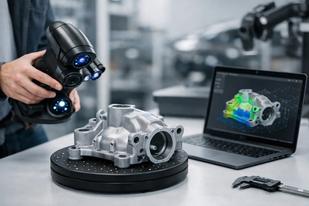
What a reverse engineering 3D scanning service actually delivers
A reverse engineering 3D scanning service captures the geometry of an existing object and converts that data into formats your team can use for design, validation, and manufacturing. Depending on the part and the end goal, that may mean a mesh file for visualization, a parametric CAD model for redesign, a 2D drawing, or a finished part made through additive or conventional manufacturing.
This is where many projects either stay efficient or become expensive. A raw scan mesh is useful for reference, but it is rarely enough for production. Engineers usually need clean surfaces, reconstructed features, datums, hole positions, wall thickness checks, and dimensional verification against functional requirements. If the part mates with other components, carries load, seals fluid, or fits within an assembly, the service has to account for those conditions before any remanufacturing method is selected.
When scanning is the right approach
Scanning makes sense when the physical part contains geometry that would be slow or impractical to measure manually. Freeform surfaces, worn legacy components, hand-shaped models, cast parts without reliable drawings, and discontinued replacement parts are common examples.
It is also useful when the original CAD exists but no longer reflects production reality. A molded or machined component may have evolved through years of supplier-side changes. In that case, scanning helps establish an as-built baseline so engineering and procurement teams can work from current geometry rather than outdated documentation.
That said, not every part needs 3D scanning. If a component is simple, fully dimensioned, and made of standard prismatic features, direct measurement and CAD reconstruction may be faster and less costly. The right decision depends on geometry complexity, required accuracy, downstream manufacturing process, and whether cosmetic form or functional features matter more.
The workflow matters more than the scanner
For most industrial buyers, the scanner model is not the key question. The more relevant question is how the service provider controls the full workflow from capture to manufacturable output.
A typical job starts with defining the target. Is the goal to duplicate a part exactly, create a CAD model for redesign, inspect deformation, or produce a short-run replacement? That decision affects scan resolution, alignment strategy, file outputs, and tolerance planning.
The next stage is part preparation. Surface condition matters. Glossy, dark, translucent, or reflective materials can affect scan quality and may require preparation before capture. Damage and wear also need to be identified early, because a scan will faithfully record defects unless the engineering team intentionally rebuilds nominal geometry.
After capture, point cloud or mesh data is processed and cleaned. Holes are filled where appropriate, noise is removed, and key features are isolated. For engineering use, this is usually followed by CAD reconstruction. That can involve prismatic feature modeling, freeform surfacing, or hybrid modeling depending on the part.
Then comes validation. This step separates a basic scan bureau from a manufacturing partner. Critical dimensions should be checked against the source part and, where available, any drawings, mating components, or known functional requirements. If the output will be used for CNC machining, molding, or metal printing, manufacturability should be reviewed before release.
Accuracy is contextual, not absolute
One of the most common misunderstandings in reverse engineering projects is treating scanner accuracy as a single answer. In practice, accuracy depends on part size, material, geometry, accessibility, fixturing, scan strategy, and the quality of post-processing.
A small intricate component may need fine feature capture, but the final CAD model still has to reflect design intent rather than every random imperfection on a used part. A large housing may be easy to scan overall but difficult to validate at critical interfaces. Internal features present another limitation. If geometry is hidden, external scanning alone may not provide complete data, and another inspection method may be required.
For production parts, the important question is whether the recovered geometry is accurate enough for its intended process and function. A cosmetic shroud, a fixture nest, and a sealing surface do not carry the same tolerance risk. Good service providers define acceptable tolerances at the beginning instead of relying on generic scan claims.
From scanned part to manufactured part
This is where engineering teams gain real leverage. Once geometry has been reconstructed and validated, the next step is choosing the right production route.
If speed is the priority and the application allows it, polymer additive manufacturing can produce functional replacements, test-fit models, housings, jigs, or low-volume end-use parts quickly. For example, HP Multi Jet Fusion or SLS may suit durable nylon parts in PA12 or PA11, especially where strength, repeatability, and short-run production matter. SLA can be suitable when surface quality and fine detail are more important than long-term mechanical performance.
If the part requires tighter machined interfaces, high heat resistance, or metal properties, CNC machining or metal additive processes such as SLM may be more appropriate. Materials like AlSi10Mg or SS316L can support demanding applications, but only if the reverse-engineered model has been built with the manufacturing method in mind. Wall thickness, support strategy, machining stock, and post-processing all affect the final outcome.
For legacy components that will be needed repeatedly, it may be smarter to scan once, rebuild the CAD properly, and then move to injection molding, urethane casting, or sheet metal fabrication depending on volume and function. That is often a better long-term decision than repeatedly reproducing a flawed one-off part.
Cost and lead time depend on what you need at the end
Teams often ask for a scan quote when they actually need a finished replacement part. Those are different scopes. A mesh export is typically faster than a fully parametric CAD rebuild. A cosmetic replica is simpler than a functionally verified component with mating checks and production planning.
Lead time is influenced by part complexity, the amount of manual CAD reconstruction required, validation needs, and whether manufacturing is included in the same project. Damaged parts can add time because engineering judgment is needed to distinguish wear from intended geometry. Assemblies also increase scope, especially when multiple components must fit together after reconstruction.
This is why a one-stop manufacturing partner can reduce delays. When the same team handles reverse engineering, process selection, production, and finishing, there is less handoff risk between scanning, design cleanup, and fabrication. Additive3D Asia approaches these projects through the same decision-led model used across prototyping and production – define the requirement, select the right process, validate manufacturability, and deliver against a controlled workflow.
What to ask before you send a part
Before starting a reverse engineering 3D scanning service, define what success looks like. Do you need a printable mesh, editable CAD, inspection report, technical drawing, or a manufactured replacement? If the part interfaces with other components, provide those details early. If certain dimensions are critical, identify them upfront rather than after the model is built.
It also helps to be clear about part condition. A new sample usually shortens the job. A worn or broken sample can still be used, but reconstruction will involve more assumptions. If there are known material, finish, or application requirements, include them from the beginning. That improves both quoting accuracy and process selection.
The best outcomes come from treating reverse engineering as an engineering transfer problem, not a scanning task. The objective is to recover useful manufacturing data with enough confidence to move into prototyping, validation, or production without repeated rework.
A good reverse engineering project does not end when the scan is complete. It ends when your team has a part, a model, or a production path it can rely on.