

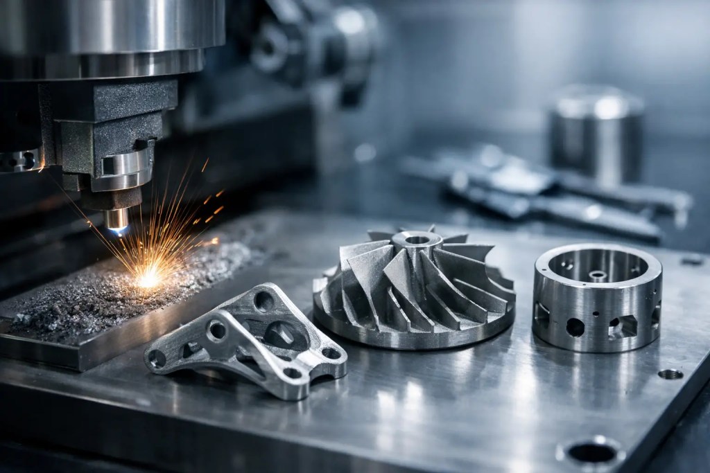
A metal part can be geometrically possible and still be a poor manufacturing decision. Internal channels may be impossible to clean, thin walls may distort during the build, or a critical bore may require machining after printing. This guide to metal additive manufacturing is written for engineers and product teams that need to decide when metal 3D printing provides a measurable advantage – and how to specify parts that can be produced consistently.
Metal additive manufacturing is not a replacement for every CNC-machined, cast, or fabricated component. It is a production method with distinct strengths: complex geometry, weight reduction, part consolidation, rapid iteration, and low-volume manufacturing without dedicated tooling. The right decision starts with the function of the part, not the novelty of the process.
What Metal Additive Manufacturing Produces
Industrial metal additive manufacturing commonly uses selective laser melting, also called SLM or laser powder bed fusion. A recoater spreads a thin layer of metal powder across a build plate. A laser selectively melts the powder according to the CAD data, then the process repeats layer by layer until the component is complete.
The result is a near-net-shape metal part that requires controlled post-processing. Unlike polymer printing, metal printing is not a simple print-and-ship workflow. Parts are built on support structures, undergo stress relief, are removed from the build plate, and may need machining, heat treatment, surface finishing, or inspection before release.
For engineering teams, the practical value is design freedom where conventional tools cannot reach. This includes conformal cooling channels in tooling inserts, lightweight brackets with optimized load paths, compact manifolds, and assemblies consolidated into fewer components. The value falls when a part is simple, high-volume, or easily produced from standard stock with conventional machining.
Guide to Metal Additive Manufacturing Process Selection
The first process decision is usually whether additive manufacturing is appropriate at all. Metal SLM is well suited to low-volume and high-complexity components, especially when lead time for tooling would delay a project. It is also useful when a design must change frequently during validation or when the geometry removes multiple joining operations.
CNC machining remains a better fit for many prismatic parts, tight-tolerance bores, flat sealing surfaces, and components produced in larger quantities. Casting and metal injection molding can become more economical when demand justifies tooling investment. Sheet metal fabrication is usually the more direct option for formed enclosures, brackets, and panels.
A capable manufacturing partner should assess these routes as part of the quotation process. The objective is not to force a part into additive manufacturing. It is to select the process that meets mechanical, dimensional, commercial, and delivery requirements with the least production risk.
Start With the Load Case
Specify what the part must do before selecting an alloy. Define static load, cyclic load, operating temperature, corrosion exposure, electrical requirements, pressure conditions, and safety implications. A lightweight aerospace bracket and a chemical-processing manifold may both benefit from additive geometry, but their material selection and validation plans are entirely different.
AlSi10Mg is often selected for lightweight components where good strength-to-weight performance and thermal conductivity are required. SS316L is suited to many corrosion-resistant applications and offers a familiar stainless steel option for industrial equipment. Other alloys may be necessary for high-temperature, high-strength, or application-specific requirements.
Published material properties are useful starting points, not automatic design allowables. Build orientation, thermal treatment, density, surface condition, and post-machining all affect final performance. For critical components, define the required mechanical properties, inspection scope, and acceptance criteria before production begins.
Design for the Build, Not Just the CAD Model
A CAD model intended for machining rarely transfers directly to SLM without modification. Design for additive manufacturing considers the physics of heat, powder, and support removal as early as possible.
Wall thickness must be adequate for the chosen material and geometry. Very thin features can warp, fail to form consistently, or become difficult to inspect. Large flat surfaces may accumulate residual stress and distort, particularly if they are not supported or if the part has uneven heat distribution during the build.
Overhangs often require support structures. Those supports anchor the component, manage thermal stress, and prevent downward-facing surfaces from degrading. They also leave marks after removal. If a surface requires a fine finish or a precise interface, orient it where support removal and finishing are practical, or plan for secondary machining.
Internal channels deserve particular attention. Additive manufacturing can create paths that drills cannot, but powder must be removed after the build. Design channels with suitable diameters, smooth transitions, access points, and drainage paths. A complex cooling circuit offers little benefit if trapped powder cannot be reliably cleared or if the required internal surface roughness restricts flow.
Part orientation is also an engineering decision. It affects support volume, build time, surface finish, distortion risk, and mechanical behavior. The shortest build height is not always the best orientation. A production review should balance throughput with accessibility, tolerances, and post-processing requirements.
Tolerances and Surface Finish Need a Secondary Plan
Metal SLM produces near-net-shape geometry, not machined geometry. As-built surfaces have a different texture from milled or turned surfaces, and dimensional variation depends on feature size, orientation, thermal behavior, and process controls.
Use additive manufacturing for the geometry that benefits from it, then machine the features that control assembly and function. Typical candidates include bearing seats, threaded holes, datum faces, sealing surfaces, precision bores, and close-fit interfaces. Designing machining allowance into those surfaces prevents an otherwise successful print from being rejected during finishing.
Surface finishing should be tied to functional need. Bead blasting can improve visual consistency and remove loose particles. Machining delivers controlled dimensions and lower roughness on accessible areas. Polishing, coating, or other post-processing may be appropriate for fluid contact surfaces, cosmetic parts, or wear applications. Each operation adds cost and lead time, so specify it where it changes performance rather than by default.
Build Quality Is a System, Not a Single Inspection
A reliable metal part depends on more than the printer. Powder handling, machine parameters, build preparation, operator procedures, heat treatment, post-processing, and inspection all influence the result. This is why quality systems matter when parts move beyond early prototypes.
For development parts, visual inspection and dimensional checks may be sufficient. For functional or end-use components, the inspection plan should match the consequences of failure. That may include critical-dimension measurement, density assessment, material certification, surface verification, or nondestructive testing where appropriate.
Traceability should be proportionate to the application. At minimum, teams should be able to identify the material, process route, post-processing operations, and inspection requirements used for a production order. An ISO 9001:2015 quality management system provides a structured framework for controlling these workflows, but the actual inspection requirements still need to be defined for each part.
Cost and Lead Time: What Actually Drives Them
Metal additive pricing is influenced by more than part volume. Build height affects machine time. Total material volume affects powder use. Support structures increase both build and finishing work. Parts sharing a build plate can improve efficiency, while large single parts may occupy capacity for long periods.
Post-processing is often the largest source of variation. A simple stress-relieved part with basic support removal may be delivered quickly. A component requiring heat treatment, precision machining, threaded inserts, specialized finishing, and detailed inspection will require more planning. That does not make additive manufacturing slow; it means realistic lead time must account for the complete production route.
Design consolidation can offset these costs. Replacing a welded assembly of several components with one printed part may reduce procurement, assembly labor, inventory, and failure points. The best business case considers total system cost, not only the unit price of the printed component.
A Practical Production Workflow
The most efficient projects begin with a clean CAD file in STEP format when possible, along with an STL file if requested for quoting. Include the intended material, quantity, key tolerances, finishing requirements, and the part’s operating environment. Mark critical features clearly rather than applying unnecessarily tight tolerances across the entire drawing.
Once manufacturability is reviewed, the manufacturer can recommend orientation, supports, machining allowances, and post-processing. This early exchange is where most avoidable problems are prevented. It is considerably faster to modify a channel exit or datum surface in CAD than to discover the limitation after a completed build.
Additive3D Asia supports this workflow by combining industrial metal SLM with machining, surface finishing, and other conventional processes. For teams managing prototype-to-production transitions, that broader capability can reduce handoffs between vendors and keep the process route aligned as volumes or design requirements change.
Make the First Build a Learning Asset
The first metal additive build should answer more than whether the part looks correct. Use it to confirm fit, assembly sequence, load performance, finishing access, and inspection strategy. Record what changed during build preparation and what post-processing was required to meet the drawing.
That knowledge turns the next order into a controlled manufacturing decision rather than another experiment. When the geometry, alloy, post-processing route, and acceptance criteria are defined together, metal additive manufacturing becomes a dependable route to parts that conventional methods cannot produce as efficiently.