

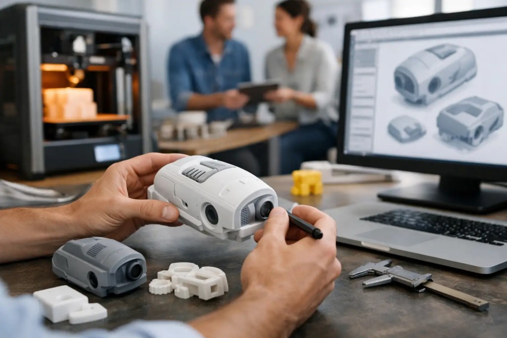
A prototype that arrives quickly but answers the wrong question is still a delay. That is why a practical guide to rapid prototyping workflows starts with decision quality, not machine speed. Engineers and product teams move faster when each build has a defined purpose, the right process, and a controlled handoff into the next iteration.
Rapid prototyping is often described as a way to compress development time. In practice, the bigger value is reducing uncertainty in a structured way. A good workflow helps teams test fit before finish, function before tooling, and manufacturability before volume commitments. It also prevents a common failure mode: treating every prototype as if it needs the highest possible cosmetic standard or the fastest possible turnaround, regardless of what the program actually needs.
What a rapid prototyping workflow is really solving
The workflow exists to answer specific technical and commercial questions in sequence. Early in development, those questions are usually geometric. Does the assembly fit? Are clearances adequate? Can a technician install the component without forcing it? At that stage, speed and dimensional confidence matter more than surface perfection.
As the design matures, the questions shift. Now the team may need mechanical performance, thermal behavior, chemical resistance, or a more production-like finish. Later still, the prototype may need to support customer demos, pilot builds, regulatory review, or manufacturing validation. Each of those stages changes the right choice of process, material, tolerance strategy, and post-processing.
That is why strong workflows are stage-gated. They do not ask one prototype to do everything. They match the build objective to the manufacturing method and keep iteration cycles short and measurable.
Build the workflow around prototype intent
The fastest way to lose time is to skip intent definition. Before uploading a CAD file or requesting a quote, the team should decide what the part must prove. In most programs, prototype intent falls into four categories: visual review, fit and assembly, functional testing, and production readiness.
Visual review parts are used to assess form, ergonomics, and stakeholder alignment. These may prioritize fine detail and surface appearance over strength. Fit and assembly parts are meant to validate dimensions, interfaces, and installation sequence. Functional prototypes push the part under load, heat, or repeated use, so material behavior becomes critical. Production-ready prototypes sit closest to end-use conditions and often need tighter process control, secondary finishing, and clearer documentation.
These categories can overlap, but combining too many objectives into one build usually increases cost without improving decisions. If a prototype only needs to validate envelope and mounting points, a lower-cost polymer process may be the correct choice. If the goal is to test a bracket under real operating loads, then process and material selection need to reflect actual service conditions.
Guide to rapid prototyping workflows by stage
A reliable guide to rapid prototyping workflows follows the product development path from concept to pre-production. The exact sequence varies by industry, but the logic is consistent.
Stage 1: Concept validation
At the concept stage, the goal is speed. Teams need parts in hand quickly to review geometry, packaging, and design direction. This is where additive manufacturing typically provides the most immediate value because it removes tooling lead times and supports frequent CAD updates.
For simple visual and fit checks, engineers often benefit from choosing a process that balances turnaround, part size, and baseline dimensional stability. The key is not chasing unnecessary material performance. If the part is only being used to review internal clearances or user interaction, paying for engineering-grade properties can be wasteful.
At this stage, document what was learned from the build. Not just whether the part looked right, but whether holes aligned, snap features assembled, and support removal or orientation affected critical surfaces. Those observations improve the next revision more than a generic note saying the prototype was approved.
Stage 2: Engineering iteration
Once geometry is directionally correct, the workflow should shift to engineering iteration. Now the team is evaluating strength, stiffness, heat exposure, wear, and actual use conditions. This is where process selection becomes more consequential.
For polymer parts, technologies such as HP Multi Jet Fusion and SLS are often selected for functional prototypes because they produce durable parts suitable for repeated handling and assembly trials. SLA can be useful where fine detail or smoother surfaces are needed, though resin performance must be assessed carefully against mechanical requirements. FDM remains useful for certain low-cost validation tasks, especially when speed and accessibility matter more than isotropic properties or surface quality.
For metal components, SLM can help validate geometry and functional performance where polymer substitutes would be misleading. Materials like AlSi10Mg or SS316L are relevant when the prototype must reflect weight, corrosion resistance, or thermal behavior closer to the final application. The trade-off is cost and post-processing complexity, so metal should be chosen because the test requires it, not because the part may eventually be metal in production.
Stage 3: Design for manufacturability
This is the stage many teams under-resource. A prototype can pass bench testing and still fail as a production candidate because the design was never evaluated against the realities of manufacturing. The workflow should now include manufacturability feedback, tolerance review, and decisions about whether the part should remain additive or transition to CNC machining, injection molding, vacuum casting, or sheet metal fabrication.
This is where a multi-process supplier becomes useful. The question is no longer which prototyping method is fastest. The question is which method produces the right result at the next volume and quality threshold. A housing that works well in MJF for ten units may need injection molding at scale. A machined critical interface may need to stay subtractive even if the surrounding geometry remains additive. Good workflows account for those transitions early so the prototype does not create false confidence.
Stage 4: Pilot and pre-production
By the time a part reaches pilot builds, repeatability matters as much as speed. Teams need controlled revisions, stable specifications, and traceable quality checks. Cosmetic requirements may increase, but so does the need for process discipline.
At this stage, post-processing should be treated as part of the workflow, not an afterthought. Sanding, vapor smoothing, machining, coating, bead blasting, and thread insertion can all affect dimensions, surface quality, and delivery time. If a part is heading into customer evaluation or low-volume deployment, those operations must be defined upfront.
Choosing the right process without slowing procurement
Process selection should be based on what the prototype must prove, how many units are needed, and what downstream step comes next. Material and process decisions are rarely absolute. PA12 may be a strong general-purpose choice for many functional polymer parts, but PA11 may be better where ductility matters. SLA may deliver better detail, but not always the best long-term performance. CNC machining may provide tighter tolerances on critical surfaces, but it can be inefficient for complex internal geometries that additive handles easily.
The practical answer is to narrow choices by requirement. If the part needs functional strength and moderate complexity, powder-bed polymer processes often make sense. If it needs very fine features or display-grade appearance, resin-based processes can be appropriate. If the part must reflect end-use metal behavior, metal additive or machining may be justified. If quantities are increasing and unit economics are changing, molding or casting may be the right next step.
A structured quoting workflow helps here. When teams can upload CAD, identify requirements, receive manufacturability guidance, and compare options quickly, they reduce idle decision time between revisions. That matters as much as machine lead time because many product delays happen before production starts.
Common workflow mistakes that create rework
Most prototyping delays come from preventable issues. One is using incomplete CAD and expecting the manufacturer to infer design intent. Another is sending files without identifying critical dimensions, mating features, or cosmetic surfaces. A third is selecting a process based only on price or only on speed.
Revision control is another weak point. When teams circulate multiple file versions across engineering, procurement, and suppliers, incorrect builds become more likely. The fix is straightforward: lock naming conventions, attach revision status to every RFQ, and state whether the part is for fit, function, or appearance.
It also helps to distinguish target tolerances from preferred tolerances. Not every surface needs the same control. If you specify tight tolerances everywhere, cost goes up and lead time often follows. If you define only the dimensions that matter, the workflow stays efficient and the prototype remains fit for purpose.
Where quality systems matter in rapid prototyping workflows
Speed matters, but repeatability is what makes rapid prototyping useful across multiple iterations. When the workflow is supported by standardized inspection, documented production methods, and formal quality management, teams can compare revisions with more confidence.
For engineering organizations working on regulated products, industrial equipment, or customer-facing hardware, that consistency is not optional. ISO 9001:2015-aligned processes, controlled documentation, and traceable production steps reduce procurement risk and make prototype outcomes easier to trust. That is especially valuable when the same manufacturing partner may later support bridge production or end-use parts.
A capable supplier should not just produce the file as submitted. They should flag manufacturability concerns, recommend a more suitable process when necessary, and help the team avoid choices that look fast on paper but create delays in the next phase. That operational role is where a service bureau such as Additive3D Asia adds value beyond machine access.
The best workflow is the one that answers one important question per build, preserves learning between revisions, and makes the next manufacturing decision easier. If your prototypes are arriving on time but your program still feels slow, the problem is usually not printing speed. It is workflow design.