

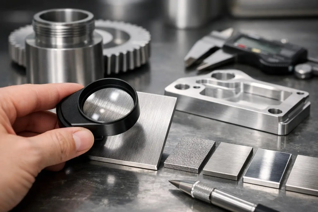
A surface finish callout can determine whether a part seals correctly, slides without galling, accepts a coating, or arrives with unnecessary machining cost. Knowing how to specify surface finish for production parts means translating functional requirements into measurable, process-capable instructions. A note such as “smooth finish” leaves too much open to interpretation and can produce inconsistent results across suppliers, materials, and manufacturing routes.
For production parts, the specification should define only what the part needs to perform. Surface finish is not a cosmetic afterthought. It affects friction, wear, fatigue performance, corrosion behavior, mating fit, cleanability, paint adhesion, and inspection acceptance.
Start With the Function of Each Surface
Do not apply one finish requirement to the entire component by default. Identify the surfaces that interface with another part, fluid, seal, coating, or user. Those are the locations where finish requirements need engineering attention.
A bearing seat, for example, may require a controlled machined finish to maintain contact and assembly force. A gasket face may need a sufficiently smooth finish to support sealing, but an excessively polished surface can sometimes reduce gasket grip. An external housing surface may only need a consistent cosmetic appearance after bead blasting or vapor smoothing. These are different requirements and should receive different callouts.
Before selecting a number, establish what the surface must achieve. Consider four questions:
- Does it mate, slide, seal, locate, or carry a coating?
- Is the surface visible or handled by an end user?
- Does it need to be measured as a critical dimension after finishing?
- Will the part be manufactured by additive processes, CNC machining, molding, casting, or a combination of processes?
This functional approach prevents over-specification. Calling out a low roughness value on noncritical surfaces can add secondary operations, increase lead time, and raise unit cost without improving part performance.
Use a Measurable Surface Finish Parameter
For most engineering drawings, roughness average, written as Ra, is the most familiar and practical parameter. Ra describes the average height variation of a surface profile, commonly specified in micrometers or microinches. A lower Ra value generally indicates a smoother surface, but Ra alone does not describe every characteristic that may affect function.
Use the unit system consistently with the drawing. For US-based teams, microinches may be common on legacy drawings, while micrometers are widely used in global supply chains. State the unit beside the requirement rather than assuming it. For reference, 1.6 µm Ra is approximately 63 µin Ra.
Ra is suitable for many machined, molded, and finished additive parts. However, it can be insufficient when the direction or spacing of surface texture matters. Sealing faces, sliding components, and surfaces with controlled lubricant retention may require additional parameters such as Rz, waviness, or a defined lay direction. Specify these only when the application justifies the added inspection requirement.
A practical specification might read: “Machined sealing face: Ra 1.6 µm maximum, measured after final finishing.” That communicates the applicable feature, maximum allowable roughness, unit, and inspection condition.
Match the Requirement to the Manufacturing Process
Every manufacturing process has an attainable surface range, and the starting condition matters. A finish that is routine for a CNC-milled aluminum part may require extensive post-processing on a laser powder bed fusion metal component or an additive polymer part.
CNC machining can produce controlled finishes on accessible surfaces through tool selection, spindle speed, feed rate, step-over, and final passes. A standard machined finish is often appropriate for functional interfaces. Tighter values may require grinding, honing, lapping, or polishing, particularly for bores, sealing faces, and precision sliding features.
Injection molding can create smooth surfaces directly from the tool, but the mold finish, resin, part geometry, draft, and texture all influence the result. If a molded cosmetic surface requires a specific texture or gloss, identify the recognized mold texture standard or approved visual sample, not merely an Ra value.
For polymer additive manufacturing, surface texture varies by technology and orientation. HP Multi Jet Fusion and SLS parts typically have a fine, matte texture that is suitable for functional housings, jigs, and low-volume production components, but it is not equivalent to a machined finish. Vapor smoothing, bead blasting, dyeing, coating, or machining can improve appearance and selected functional surfaces. Build orientation should be considered because upward-facing, downward-facing, and angled surfaces may not finish alike.
SLA can provide high detail resolution and a comparatively smooth as-printed appearance, but support contact points and post-curing still affect final quality. FDM produces visible layer lines unless post-processing is applied. For metal SLM parts in materials such as AlSi10Mg and SS316L, as-built surfaces are usually rougher than machined surfaces. Critical interfaces should be designed with machining stock and accessible tool paths whenever possible.
The production route should be explicit when it affects the requirement. Rather than asking for an entire metal additive part to meet a machined Ra value, specify machined critical faces and define an acceptable as-built or blasted condition for remaining surfaces.
Place Callouts Where They Can Be Produced and Inspected
A correct finish value is not useful if the supplier cannot reach or inspect the surface. Deep pockets, narrow internal channels, sharp corners, threads, lattice structures, and enclosed cavities all limit finishing access and profilometer use.
Design for the post-process from the start. If a surface needs machining, provide tool clearance and a datum strategy. Add material allowance to additive or cast features that will be machined. If polishing is required, account for edge rounding and dimensional change. If the part will be bead blasted or chemically smoothed, identify surfaces where dimensional growth or material removal could affect fit.
On the drawing, use the surface texture symbol and leader to point to the applicable face. A general note can define a baseline finish for all unspecified surfaces, while local callouts control critical areas. This is more effective than applying a tight general requirement that forces unnecessary processing across the entire part.
For example, a production enclosure could use a general note for an as-manufactured exterior, a local machined Ra callout for an O-ring groove face, and a separate cosmetic requirement for the customer-facing panel. Each requirement serves a distinct purpose and can be quoted accurately.
Define Inspection and Acceptance Criteria
Surface finish is a measurable quality characteristic, but measurement conditions affect results. The cutoff length, instrument type, filter settings, measurement direction, and sampled location can all influence a reading. For highly controlled applications, include the relevant standard and measurement method in the drawing, purchase specification, or quality plan.
Most production projects do not need a fully detailed metrology procedure on every feature. They do need agreement on whether the value is a maximum, a target range, or a reference value. A maximum Ra is usually the clearest approach for functional requirements. A target range can be useful where surfaces must not be too smooth or too rough.
Visual standards also have a place, especially for cosmetic parts. Color, gloss, blast uniformity, support marks, sink, flow lines, and other appearance attributes are not always captured by an Ra reading. For those parts, pair measurable requirements with an approved sample, clear photographs, or a defined cosmetic acceptance class.
ISO 9001:2015 quality systems support controlled documentation and repeatable inspection workflows, but they do not replace a complete engineering requirement. The drawing and purchase order should still identify what matters, where it matters, and how acceptance will be determined.
Balance Finish, Tolerance, and Cost
Surface finish interacts directly with dimensional tolerance. A polished surface can remove material. A coating can add thickness. Vapor smoothing can change fine features and edge definition. If a bore must hold a tight fit after finishing, specify the final dimension and finish condition together.
The same principle applies to additive manufacturing. A PA12 part may be ideal for a lightweight functional enclosure with a bead-blasted or vapor-smoothed exterior, while a precision locating feature may need a machined insert or post-machined datum surface. A hybrid process is often the most reliable route to production performance.
When requesting a quote, provide the CAD model, drawing, material, finish callouts, quantity, and intended application. If the finish is cosmetic, include the required appearance level. If it is functional, describe the mating condition, fluid exposure, load, temperature, or movement involved. That information allows the manufacturing team to recommend a process that meets the requirement without adding avoidable operations.
How to Specify Surface Finish for Production Parts Without Over-Specifying
The best specifications are selective. Define a general surface condition for the part, then tighten requirements only on surfaces that affect performance, assembly, sealing, or appearance. Use Ra where it is meaningful, specify units and limits, and make sure the feature is accessible for both finishing and inspection.
For a production-ready drawing, a manufacturer should be able to answer three questions without guessing: which surfaces are critical, what finish is required after all post-processing, and what evidence establishes acceptance. If those answers are clear, process selection, pricing, and quality control become substantially more predictable.
A short design review before release can save more time than a late-stage rework cycle. Additive3D Asia can assess the relationship between material, manufacturing method, machining access, and post-processing so the specified finish supports the part’s actual production function.