

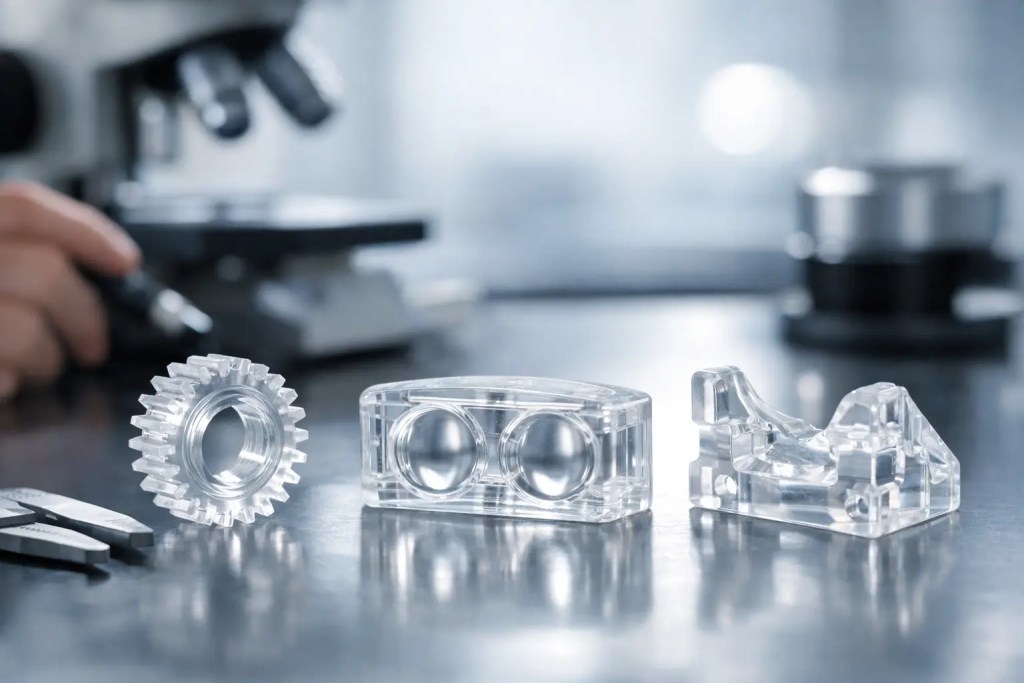
A transparent prototype can look convincing on a bench and still produce misleading optical results. Clear resin parts for optical validation must be assessed as functional test articles, not presentation models. Internal scatter, surface waviness, layer geometry, post-cure effects, and residual support marks can all change how light travels through a part.
For engineers developing light guides, sensor covers, illuminated controls, fluidic inspection devices, lenses, and optical enclosures, the question is not simply whether a part is clear. The relevant question is whether its optical behavior is controlled well enough to validate the design decision at hand. That distinction determines the material, printing process, finishing route, and inspection plan.
Define What the Optical Test Must Prove
Optical validation has different requirements at different stages of development. A concept model may only need to show that an LED is visible through a cover. An engineering prototype may need to compare light output at a sensor, identify hot spots in an illuminated housing, or check whether a viewing window introduces glare. A qualification build may require repeatable transmission, haze, color, and dimensional results across multiple units.
These are not equivalent requirements. A resin part that is appropriate for checking component fit and approximate light diffusion may be unsuitable for evaluating image sharpness or measured transmission. Before selecting a process, define the test condition, light source, wavelength range, detector or viewing angle, acceptable variation, and whether the part will be tested dry, immersed, heated, or exposed to UV.
It also helps to separate optical function from optical appearance. A polished surface can improve visual transparency while leaving internal refractive-index variation or geometry error that affects the measurement. Conversely, a deliberately frosted surface may be correct for a diffuser even though it does not look optically clear.
Where Clear Resin Parts for Optical Validation Fit
SLA is often the most practical additive process for early optical prototypes because it can produce fine features, thin walls, smooth as-printed surfaces, and transparent resin parts with short lead times. It is particularly useful when the design includes complex internal channels, light baffles, snap features, mounting points, or enclosures that would be costly to machine during the first iterations.
Typical applications include LED light pipes, translucent covers, optical sensor housings, alignment fixtures, viewing ports, flow-cell concepts, and illumination prototypes. The value is speed: engineering teams can test an integrated design rather than evaluate a flat sample of material disconnected from the final geometry.
The boundary is equally important. Standard clear photopolymer resin should not be assumed to replace injection-molded optical-grade polycarbonate, PMMA, cyclic olefin polymer, or precision glass. For imaging optics, high-power laser paths, tightly specified refractive properties, or outdoor long-term exposure, a printed resin prototype may establish directional performance but not final-product equivalence. In those cases, CNC machining, molding, or a specialized optical fabrication route may be required for final validation.
Material Selection Starts With the Light Path
Clear resins are formulated differently, and their published transparency is only one selection factor. The part may yellow after post-curing, absorb at certain wavelengths, develop haze after cleaning, or change behavior when exposed to heat and humidity. If the application relies on UV, blue light, infrared sensing, or a camera-based measurement, test the resin under the actual source rather than judging it under room lighting.
Wall thickness also matters. A 1 mm clear wall can appear highly transparent while a 6 mm section of the same resin shows visible tint, scatter, or reduced transmission. Longer optical paths amplify small material and surface effects. This is common in thick light guides, solid blocks, and enclosed fluidic geometries.
For a diffuser, controlled haze may improve uniformity by breaking up source images and reducing hot spots. For a sensor window or light guide, that same haze can reduce signal strength or create unwanted cross-talk. The correct resin is therefore tied to the function of the surface: transmit, redirect, diffuse, contain, or protect.
Request material data relevant to the design decision, then confirm performance with representative coupons and finished parts. A flat transmission coupon is useful, but it should not replace testing the actual geometry. Curves, ribs, bosses, and changes in wall thickness introduce optical behavior that a simple plaque will not reveal.
Design Geometry Around Process Reality
Optical surfaces should be designed with the build process in mind. Any surface that matters to the measurement should be accessible for cleaning and finishing. Deep cavities, narrow channels, and enclosed volumes can retain uncured resin or cleaning fluid, creating haze and unpredictable scatter after post-processing.
Avoid placing critical optical faces where supports will contact them. Support removal leaves localized marks, and even small imperfections can become visible when light is directed through or reflected from the surface. Orienting the part so the critical face is upward or otherwise support-free can reduce finishing work, although the best orientation may require a trade-off with dimensional accuracy, peel forces, or build stability.
Sharp transitions are another common source of optical artifacts. A sudden thickness change can create a visible line, change light distribution, or concentrate stress during curing. Where function allows, use gradual transitions and consistent wall sections along the light path. If a feature must create an optical edge, specify it intentionally and validate it as a controlled feature rather than accepting it as a printing byproduct.
Dimensional tolerances remain essential. A clear part can be visually transparent but fail its intended purpose if an LED, sensor, gasket, or lens seats in the wrong location. Build tolerances, shrinkage compensation, and post-processing stock should be discussed alongside optical requirements.
Finishing Has a Direct Optical Effect
As-printed clear resin is rarely the final condition for meaningful optical testing. Layer lines and surface texture scatter light. Cleaning residues, incomplete curing, and aggressive sanding can add haze. The finishing plan should be included in the prototype specification from the beginning.
A typical route may include controlled washing, support removal, UV post-curing, staged wet sanding, polishing, and a compatible clear coating where appropriate. Each operation changes the surface and can alter dimensions, especially on thin walls and small features. Coatings can improve apparent clarity and seal micro-scratches, but they can also add thickness, create edge buildup, yellow over time, or have a different refractive index from the base resin.
For comparison testing, keep the finishing method consistent across all samples. A polished part should not be compared directly with an as-printed part if the goal is to judge geometry or material changes. Record the build orientation, resin batch, wash procedure, cure cycle, and finishing sequence. That process traceability makes it possible to distinguish a design issue from a manufacturing-variable issue.
Additive3D Asia applies an ISO 9001:2015 quality framework to process control and can advise on whether SLA, CNC machining, urethane casting, or another production route better matches the validation objective. This matters when the prototype program must progress from a fast printed iteration to a material and surface condition closer to production.
Inspect the Parts Before Trusting the Data
Optical validation is stronger when the part itself is inspected before the system test. Start with visual checks under both diffuse and directed light. Look for support scars, trapped resin, internal voids, cure gradients, surface scratches, coating defects, and visible yellowing. Then inspect dimensions and critical optical interfaces using the appropriate measurement method.
For quantitative work, establish a reference condition. Compare the printed part against an open optical path, a known reference window, or a production-intent sample. Measure the same positions and angles across each build. If haze, transmission, luminous intensity, sensor output, or image contrast is being evaluated, document the source settings, detector configuration, ambient light condition, and part orientation.
Replication is often more valuable than chasing a single ideal sample. Testing three to five parts from the same controlled process can reveal whether a result is repeatable. If the variation is too large for the engineering decision, the next step may be a revised orientation or finishing process rather than a redesign of the optical system.
Choose the Prototype Route Based on Decision Risk
Clear SLA resin is an efficient choice when the team needs to validate geometry, assembly, light distribution trends, and early functional performance quickly. It is less suitable when the decision depends on certified optical properties, long-term environmental stability, extremely low haze, or precision lens quality.
Use the lowest-risk manufacturing route that can answer the current question. Early concepts may justify a clear printed resin part. A later design gate may call for CNC-machined PMMA or polycarbonate. If the design is approaching short-run production, urethane casting or injection molding may provide a more representative surface and material condition.
The useful outcome is not a prototype that looks perfectly transparent. It is a controlled part that gives the engineering team reliable evidence for the next manufacturing decision.