

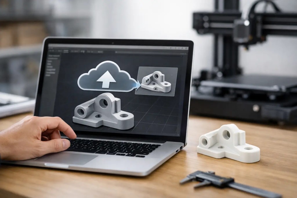
A fast quote means very little if the file behind it is not production-ready. When engineers ask how to upload STL files for manufacturing, the real question is usually how to submit a file that clears review quickly, matches the intended process, and produces parts without avoidable revisions.
An STL is simple by design. It describes surface geometry as a mesh of triangles, which makes it widely accepted across additive workflows. That same simplicity also creates risk. STL does not carry native feature history, material intent, tolerances, or assembly logic. If the mesh is poorly exported or the upload is missing critical manufacturing information, the quoting stage slows down and production decisions become less precise.
How to upload STL files for manufacturing without delays
The upload itself is usually the easiest part. The work happens before the file reaches the platform. A manufacturing-ready STL should be watertight, scaled correctly, oriented with intent if orientation matters, and paired with clear job requirements.
Start by checking whether STL is the right file type for the part. For many 3D printed components, STL is acceptable and expected. For machined parts, tightly toleranced interfaces, or jobs that may move between additive and conventional processes, a STEP file often provides better geometry definition. If you are uploading an STL because the part is intended for MJF, SLS, SLA, FDM, or metal additive manufacturing, that is generally appropriate. If the part may later need CNC finishing or tooling development, include a native CAD or STEP file when possible.
Once the file type makes sense, verify the mesh. Manufacturing platforms and engineering teams look for a closed manifold body. That means no holes, no inverted normals, no non-manifold edges, and no self-intersecting surfaces. A file can look correct on screen and still fail during slicing or build preparation. Running a mesh repair check before upload saves time.
Units are another common problem. STL files do not always retain unit data reliably across software environments. A 50 mm component can appear as 50 inches or 50 microns if the export and import settings do not align. Before uploading, confirm the part dimensions in the target system and make sure the quoted size matches the design intent.
What to prepare before you upload
A clean STL alone is not enough for a dependable manufacturing handoff. The best submissions include the file plus the information needed to make the right production decision on the first pass.
Process selection comes first. Different technologies interpret the same geometry differently. An MJF part in PA12 can be excellent for functional prototypes, housings, and short-run production where strength and speed matter. SLA may suit cosmetic prototypes or parts that need finer detail and smoother surfaces. Metal SLM is appropriate for parts requiring metal performance, but support strategy, heat treatment, and post-processing become far more important. Uploading the STL without identifying the likely process leaves too much room for rework.
Material intent should be stated just as clearly. If the application calls for PA11 because ductility matters, or AlSi10Mg because weight and heat performance are part of the design requirement, say so during submission. Otherwise, engineering review has to fill in assumptions that may not match the real use case.
It also helps to specify the part function. A fixture, a visual model, a pressure-tested component, and an end-use enclosure may all share similar geometry, but they should not be reviewed the same way. Load direction, operating temperature, chemical exposure, cosmetic priority, and mating features all influence manufacturability.
If a surface matters, identify it. If a thread is critical, identify it. If a face will be machined after printing, identify it. STL does not carry semantic feature information, so these details need to be communicated separately.
How to upload STL files for manufacturing on a quote platform
Most digital manufacturing platforms follow a similar path: upload the file, review the generated geometry preview, select process and material, define quantity, add notes, and submit for quotation or direct order. What separates a smooth workflow from a slow one is the quality of the data entered at each step.
After upload, inspect the preview carefully. Do not assume the platform interpreted thin walls, internal channels, embossed text, or lattice features exactly as intended. Zoom in on edges and fine details. If the preview looks faceted beyond expectation, the mesh resolution may be too low. If small features are missing, the export settings may have simplified them.
Then set the manufacturing parameters. Choose the process that matches the part’s performance target, not just the lowest price. For example, a nylon powder-bed process may offer better isotropic behavior than filament printing for a functional bracket. A resin process may produce better detail but lower toughness. Trade-offs matter, and they should be decided before release, not after the first failed prototype.
Next, enter quantity with care. A quantity of one prototype and a quantity of 200 bridge-production units can drive very different recommendations. In some cases, the right answer may move away from additive manufacturing entirely toward urethane casting, CNC machining, or injection molding. That is why complete project context matters at upload.
Finally, use the notes field as an engineering tool, not an afterthought. Include target tolerances where relevant, call out cosmetic surfaces, note assembly fit requirements, and mention whether equivalent alternatives are acceptable if a geometry issue is found. A short, precise note can eliminate an entire email cycle.
Common STL upload problems that affect manufacturability
The most frequent issue is wall thickness. Many designs are modeled around ideal geometry, not process minimums. Thin walls may print, but they may warp, crack, or fail inspection depending on material and orientation. A quote platform may flag this automatically, but engineers should still review it themselves.
The second issue is unsupported detail. Small pins, sharp internal corners, deep holes, and long cantilevered features can behave differently depending on process. An STL gives shape, but not design rationale. That is why manufacturability feedback often requests changes even when the file uploads successfully.
The third issue is tolerance expectation. STL is a tessellated format. It is suitable for many additive applications, but it is not ideal for carrying precision requirements by itself. If the design includes bearing fits, sealing surfaces, or datum-critical features, add notes and consider whether a different source file should accompany the submission.
There is also the issue of orientation sensitivity. Some parts are functionally anisotropic, visually sensitive, or dependent on support contact locations. If build orientation affects strength, surface finish, or critical geometry, state that during upload. Otherwise, production planning may optimize for throughput rather than your preferred orientation.
File export settings that improve quote accuracy
A low-resolution STL can distort circles into polygons and flatten small features. An excessively dense STL can create large file sizes without meaningful improvement. The right export balance depends on part size, curvature, and feature scale.
As a general rule, export with enough refinement to preserve critical curves and small details while keeping the file manageable for upload and review. If the part includes sealing surfaces, snap fits, embossed labeling, or fine text, inspect those areas after export. Do not rely on default CAD export settings if the geometry is performance-critical.
It is also worth checking whether the model has been simplified for visualization or sharing. A lightweight display mesh is often not suitable for production. Make sure the file submitted for manufacturing is the final engineering version.
When STL is enough and when it is not
STL is often enough for polymer additive parts where geometry is mature and tolerances are consistent with the selected process. It is less ideal when the part will move through multiple manufacturing routes, require downstream machining, or carry strict dimensional requirements.
That does not mean STL should be avoided. It means the upload package should match the production risk. For straightforward additive jobs, an STL plus clear process and material selection may be all that is needed. For more demanding applications, adding STEP data, drawings, or notes reduces ambiguity.
An ISO 9001:2015-certified workflow is built around reducing that ambiguity early. On platforms such as Additive3D Asia, the strongest submissions are the ones that pair upload speed with disciplined engineering input. That combination improves quote accuracy, shortens review time, and reduces changes after approval.
The best upload is not the fastest one. It is the one that gives manufacturing enough information to make the part right the first time.