

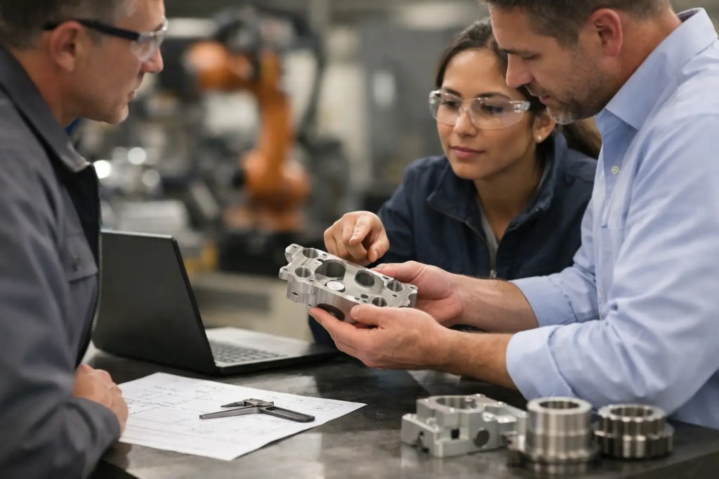
A CAD model can look complete and still fail the first production test. A thin wall may warp during printing, an internal corner may reject a standard CNC tool, or a tolerance may require inspection and finishing that the part’s function does not justify. What is manufacturability review? It is the engineering assessment that identifies these risks before a part enters production.
For product teams, the objective is not simply to confirm that a part can be made. It is to confirm that it can be made reliably, at the required quality level, with a process, material, cost, and lead time that suit the application. This distinction matters when a prototype is moving toward functional testing, a short production run, or an end-use component.
What Is Manufacturability Review?
A manufacturability review is a structured evaluation of a part design against the limitations and capabilities of the intended manufacturing process. Engineers review the CAD geometry, material requirements, critical dimensions, surface finish expectations, assembly interfaces, and production volume. They then identify features that could create quality variation, delays, unnecessary cost, or failure during fabrication.
The review is often called design for manufacturability, or DFM. DFM is the broader design discipline; a manufacturability review is the practical checkpoint where those principles are applied to a specific file and production route. The output is usually a set of actionable recommendations, not a generic pass or fail result.
For example, a review for an HP Multi Jet Fusion PA12 part may examine wall thickness, escape holes for powder removal, unsupported features, nesting orientation, and dimensional allowances. A review for an AlSi10Mg SLM component may focus more heavily on support structures, heat accumulation, internal powder removal, distortion risk, and required machining surfaces. For a CNC-machined aluminum enclosure, tool access, internal radii, stock size, clamping strategy, and tolerance callouts become central concerns.
A part can be technically manufacturable yet still be a poor production choice. If it requires multiple special setups, unusually tight tolerances, or extensive manual finishing without improving functional performance, the design needs a commercial as well as technical review.
Why Review a Design Before Manufacturing?
The earlier a design issue is found, the less expensive it is to correct. Changing a CAD feature before production may take minutes. Discovering the same issue after a print has failed, a machining program has been prepared, or a tooling order has been released can add days, scrap cost, and another procurement cycle.
Manufacturability review also protects repeatability. A single prototype can occasionally succeed under closely controlled conditions, while a run of 20, 100, or 500 parts exposes variation that was not visible on the first build. Engineers need to know whether a critical hole, sealing face, press-fit feature, or thin section will remain within an acceptable range across the planned quantity.
This is especially relevant when moving between processes. A geometry that works well in SLA for a high-detail visual prototype may not be appropriate for SLS or MJF functional parts. Similarly, a feature designed around additive manufacturing may require redesign before injection molding becomes economical at higher volumes. A good review prevents teams from treating one successful prototype as proof that the design is production-ready.
What Engineers Check During a Manufacturability Review
The details depend on the process, but the review generally starts with the part’s functional requirements. The reviewer should understand what the component must do before recommending changes. Is it a cosmetic housing, a load-bearing bracket, a fluid-carrying manifold, a locating fixture, or an electrical enclosure? A feature that appears difficult to produce may be essential. Another may be a legacy dimension with no current purpose.
Geometry and process limits
Engineers examine minimum wall thickness, small feature resolution, overhangs, unsupported spans, sharp corners, deep cavities, and enclosed volumes. Each process has different practical limits.
In polymer additive manufacturing, thin sections can be vulnerable to breakage or dimensional movement, while enclosed cavities may trap unfused powder or support material. In metal additive manufacturing, overhangs may require supports and certain shapes can concentrate heat, increasing residual stress or distortion. In CNC machining, narrow deep pockets and square internal corners can drive longer machining time or require special tooling.
The recommended change is not always to make every feature larger or simpler. It may be better to change orientation, add a radius, split a component into two parts, add a drain hole, or reserve a critical surface for secondary machining.
Material selection and part performance
Material is not a finishing choice. It influences stiffness, impact resistance, heat performance, chemical resistance, surface quality, and achievable accuracy.
A review should test whether the selected material supports the actual duty cycle. PA12 may be suitable for durable functional polymer parts, while PA11 may be preferred where higher ductility is needed. SS316L can suit corrosion-resistant metal applications, but it may not be the best choice when weight, thermal conductivity, or machining behavior is the primary concern. The right decision depends on loads, environment, regulatory needs, finishing requirements, and the consequences of failure.
Material availability also affects lead time. If a design requires an uncommon material, color, or finishing sequence, teams should account for that during planning rather than assuming every option has the same turnaround.
Tolerances and critical interfaces
Tolerances deserve careful review because they have a direct cost impact. Applying a tight tolerance to every dimension can increase inspection requirements, secondary operations, and rejection risk. It is more effective to identify the dimensions that control fit, alignment, sealing, motion, or safety, then define tolerances around those features.
This is particularly important for assemblies. Hole patterns, mating surfaces, threads, bearing seats, snap fits, and press fits need to be evaluated as a system. A printed hole may require drilling or reaming after production. A threaded feature may need an insert. A machined datum surface may be necessary to establish reliable assembly alignment.
The review should also distinguish between nominal CAD geometry and process capability. A drawing may specify a 0.1 mm tolerance, but whether that is practical depends on part size, material, orientation, geometry, and manufacturing method. Forcing an inappropriate tolerance is rarely the best answer when the design can be adjusted to achieve the same function more predictably.
Finishing, inspection, and assembly requirements
Surface finish, post-processing, and inspection need to be planned as part of the manufacturing route. Bead blasting, sanding, dyeing, painting, vapor smoothing, heat treatment, machining, and coating can improve appearance or performance, but they can also affect dimensions and lead time.
A review checks which surfaces are cosmetic, which need low roughness, and which need to remain untouched. It also defines how critical requirements will be verified. If a part requires material certification, dimensional inspection, thread gauging, or a documented quality record, these requirements should be identified before production begins.
For ISO 9001:2015-controlled production workflows, this clarity supports traceability and reduces ambiguity between the approved CAD file, purchase requirements, and finished-part acceptance criteria.
The Review Changes by Manufacturing Process
There is no universal manufacturability checklist because each production method creates different constraints. Process selection should follow the part’s requirements, not the other way around.
For 3D printing, the review balances design freedom with build stability, material behavior, and post-processing. Additive methods can reduce assemblies, create internal channels, and support complex geometries that conventional methods cannot produce efficiently. However, orientation, support removal, powder evacuation, and anisotropic properties may still affect the result.
For CNC machining, the emphasis shifts toward tool access, workholding, setup count, internal radii, and removal of material from stock. CNC is often a strong choice for tight tolerances, high-quality machined surfaces, and familiar engineering materials, but complex geometry can increase cycle time quickly.
For injection molding, draft angles, uniform wall sections, rib design, undercuts, gate location, shrinkage, and tooling complexity are major factors. The up-front design effort is greater because tooling changes are expensive, but the process can become highly efficient at scale.
Vacuum casting and sheet metal fabrication each require their own review logic as well. The right question is not which process is best in general. It is which process delivers the required part performance and quality at the planned quantity and timeline.
A Productive Review Workflow
A practical review begins with a current STL or STEP file and a concise statement of requirements: intended application, material preference, quantity, target delivery date, cosmetic expectations, critical dimensions, and any inspection needs. Without this context, a reviewer can identify geometric issues but cannot judge the correct trade-offs.
The manufacturing engineer then evaluates the file against the selected process and returns recommendations. These may include changes to wall thickness, radii, tolerances, orientation, support strategy, threads, finishing, or material. The design team decides which changes preserve function and updates the model before approval.
At Additive3D Asia, this review can be integrated into the quotation stage, helping teams evaluate production feasibility before releasing an order. That is useful when comparing additive manufacturing, CNC machining, casting, or other routes for the same component.
A manufacturability review should not be treated as a hurdle at the end of design. Use it as a decision point when the cost of change is still low and the available process options are still broad. The result is a part that is easier to quote, easier to produce, and far more likely to perform as intended when it reaches the production floor.